
Installation manual

TDB3108, WF3208 Installation
8 4/3/2013 Bradley • 215-1577 Rev. B; ECN 13-00-001
4a
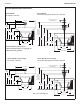
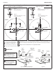
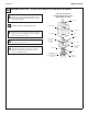
Assemble TouchTime
®
– A and O Units without Tie Pipe Option (A Shown)
A
Installhemmedend(notsharpend)of
support tube with gasket onto bowl.
B
Connect1/2"supplytubingtosprayheadwith
3/8"NPTto1/2"tubeconnectorandplace
sprayhead onto support tube. Run the tubing
down through the support tube and connect to
valve tube connector.
C
Placetheuppertiebar(notchedatbothcorners
ofeachend)ontopofsprayhead.Connectthe
longertierodtothe4-1/4"tierodusingthe
coupling nut with hex head set screws.
D
Run the tie rod assembly down through upper
tie bar and secure from underneath the bowl
usinglowertiebar(nonotches)andhexnutwith
socket head set screw.
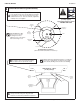
Tie Rod Pre-Pack
Cover
Actuator
Module
Assembly
Coupling
Nut
Sprayhead
Tie Bar
Tie Rod
Supply Tube
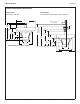
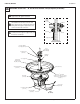
Section View of
A/O Unit Assembly
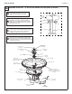
Tie Rod Pre-Pack
(S45-1336)
Top Cover
(107-099 (A))
(107-179 (O))
Module Cover
(S04-083)
Sprayhead
(S05-054)
Drain (S45-273)
Terreon
®
Deep Bowl
(Part No. Varies with color of bowl.
Contact your local Bradley Rep for
assistance)
Access Panel
(186-1456)
Valve Assembly
(S50-368)
Pedestal Assembly
(S17-242)
1/2" Supply Tube
Pre-Pack
(S45-055)
Support Tube
Gasket (125-011)
Support Tube
STD (S57-005)
TAS/JUV (S57-006)
Tie Rod (176-008A)
Tie Bar
Nut
Actuator Module Assembly
(S83-179)
A/O
(A shown)