
Installation manual

Installation TDB3108, WF3208
Bradley • 215-1577 Rev. B; ECN 13-00-001 4/3/2013 13
A
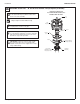
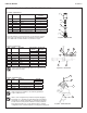
Mount the terminal block in a convenient location
using the hook and loop fastener supplied. Make
sure all wires will reach.
B
Connect the two transformer wires, the two wires from each
solenoid valve and the four wires from each TouchTime switch
to the terminal block as shown. Plug the 24 VAC Class II
transformer(S83-134)intoa110VACGFIoutlet.
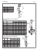
6
Make Electrical Connections for TouchTime Control
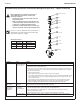
7
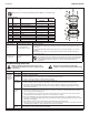
Activate Water Supply & Adjust Temperature
A
Turn supplies on. Open check/stop valves and volume control valve completely. Push the TouchTime
switch to purge air from the lines and activate water. Water will turn on when the button is released. If
the switch does not activate water, recheck electrical connections to the terminal block.
B
Checkthetemperaturewhenapproximately1.0GPMwaterow
isreachedandadjustifnecessary(therangeofthevalveis
95°F–115°F(35°C–43°C)).To adjust the temperature follow steps
CthroughG.Be sure to tighten locking nut afterward.
The Vernatherm Thermostatic Mixing valve is NOT factory preset. Upon installation,
the temperature of this valve must be checked and adjusted to ensure delivery of a
safe water temperature. Water in excess of 110°F (43°C) may cause scalding.
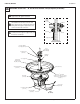
Temperature
Adjustment Screw
Temperature
Locking Nut
Solenoid
Valve
Suggested location for Terminal Block
Transformer
Transformer
Solenoid Valve
Solenoid Valve
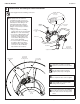
BLACK
A
B
C
D
BROWN
GREEN
GRAY
A
B
C
D
Plug-In
Transformer
S83-134
Solenoid
Valve
Wiring Diagram
TouchTime
Switches
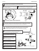
C
H
Thermostatic Mixing
Valve Assembly
C
Loosen temperature locking nut with
wrench.
E
Once desired temperature is reached,
tighten nut to prevent temperature change.
D
Usingabladescrewdriver,turnthe
adjustment stem counterclockwise to
increase the temperature or clockwise to
decrease the temperature.
F
Clean sprayhead if necessary. Adjust the
volume control to control the flow of water.
G
Attach pedestal access panel and kick
plate with hardware provided.