
Installation manual

TDB3108, WF3208 Installation
12 4/3/2013 Bradley • 215-1577 Rev. B; ECN 13-00-001
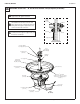
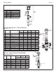
Thermostatic
Mixing Valve
Assembly S67-597
Thermostatic
Mixing Valve
Assembly S67-597
Volume Control
S02-045
Volume Control
Valve
S02-045
Solenoid
Assembly S08-
055
Flexible Hose
Filter Washer
Stop/Check Valve
1/2" Dia. Tube
from Spraynead
1/2" Dia.
Tube from
Sprayhead
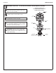
A
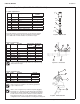
Connect1/2"dia.tubingfrom
the sprayhead to the solenoid
assembly. The male connector for
the valve assembly will remain tight
and leakproof when tubing is cut
and installed properly. Follow the
procedures below when installing
tubing to ensure that you achieve a
leakproof seal.
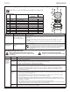
• Usingasharprazor,cuttubing
squarelyandremoveanyburrs.DO
NOTpinchorcrushendoftubing.
• Loosennutonfitting.Moistenend
of tube and push into fitting until
it is firmly seated. Tighten nut to
securetubetofitting(makesure
nutissecurelytightened).
• Ifconnectorleaks,reseattubing
according to above procedure.
If leaking persists, replace male
connector, or call your Bradley
representative for assistance.
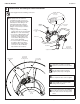
B
Hangvalveassemblyonpedestal
bracket.Usewiretietosecurevalves.
5
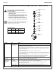
Connect Valve and Tubing for TouchTime Control
Flush supply lines before making connections.
Nut
Tubing
Male Tube
Connector
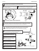
D
Attach flexible hose to thermostatic
mixing valve, two places.
C
Connectthe1/2"NPTfemaleendof
the stop/check valves to the rough-ins.
E
Insertthelterwashers(provided)into
the swivel nut at the end of the supply
hoses and connect to the stop/check
valves.
For “O” and “B” units (overhead
supplies) skip steps C through E.
Valve Mounting
Bracket