
Installation manual

5
Express® Lavatory System SS-Series
Installation Instructions SS-2N/IR/STD, SS-2N/IR/WH
Bradley Corporation • 215-1497 Rev. B; EN 03-808A 4/16/04
Installation Instructions
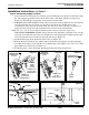
Step 1: Rough in
IMPORTANT: Flush the supply lines before making connections. Debris in supply
lines will cause the valves to malfunction.
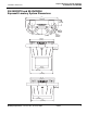
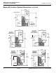
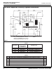
IMPORTANT: Dimensions shown in Figure 1 on page 6 are for a Standard and Wall-
Hung Pedestal Express® only. Make sure to follow appropriate
dimensions based on configuration and required rim height. See
Charts 1 and 2 on page 6 before beginning rough-ins.
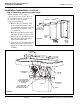
1. Rough in 1/2" NPT hot and cold supply lines through wall at dimensions shown.
2. Rough in 1-1/2" NPT drain waste connection through wall at dimensions shown.
3. OPTIONAL HOT WATER HEATER: Rough in appropriate electrical supply per local code
(recommended 240/208-volt or 277-volt electrical box location shown in Figure 1).
4. Install the 110 volt GFCI electrical outlet per local code at the location shown in Figure 1.
5. Install four to six 3/8" wall anchors with a minimum pull-out rating of 1,000 lbs. (supplied by
installer) at the locations shown in Figure 1.
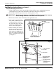
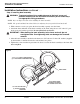
6. On the back of the bowl, measure the distance between the 3/4" bowl mounting holes. Divide
this measurement in half. Measure and mark this dimension on the wall to the left of the
centerline and to the right of the centerline. Install two 3/8" wall anchors with a minimum pull-
out rating of 1,000 lbs. (supplied by installer) at the locations marked (ref. location “A” shown in
Figure 1).
NOTE: Wall anchors at location “C” (standard frame only) do not require a minimum pull-out
rating of 1,000 lbs.
NOTE: The anchors will be used to mount the Express® bowl and frame to the wall.