
Installation manual

Other Replacement Parts
16
Express® Lavatory System SS-Series
SS-2N/IR/STD, SS-2N/IR/WH Installation Instructions
4/16/04 Bradley Corporation • 215-1497 Rev. B; EN 03-808A
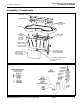
Assembly of Components
continued . . .
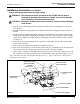
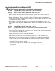
Sensor assembly and solenoid valve
To access solenoids and sensors: Remove the four Phillips-head screws located in the bottom of the
sprayhead body and lift the cover/shelf off (see components illustration on page 15 for locations).
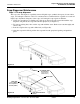
To re-install sprayhead cover/shelf: Position the cover/shelf on the sprayhead body and secure it to
the sprayhead body using the four screws provided.
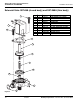
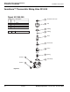
Sprayhead Components
NUT
110-115
INFRARED
WINDOW
269-1241
SCREW
160-120
STREAMFORMER
115-125
SCREW
160-289
DIFFUSER
269-508
O-RING
125-001CK
AERATOR HOUSING
115-133
1/4” ELBOW
145-090
INFRARED SENSOR
269-1608HP
#8-32 x 3/4"
ROUND HEAD
MACHINE SCREW
(160-276)
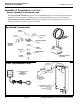
BRACKET
(140-950)
#8 WASHER
OPTIONAL WATER HEATER
EX95TMLB, 240/208 volts
(269-1767)
EX100TMLB, 277 volts
(269-1768)
#8 NUT
110/24 VAC CLASS II
PLUG-IN
TRANSFORMER
S83-152