
Installation manual

SS-3N/AST/STD, SS-3N/AST/WH Installation
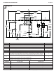
10 12/11/07 Bradley Corporation • 215-1494 Rev. E; ECN 07-814
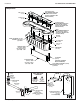
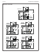
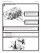
1/4" Tube
Connector
(169-890)
Spring
(135-065)
U-Cup
(125-099)
Piston
(119-227A)
Duckbill
(198-010)
Actuator
Body
(118-279)
Push Button
(S08-324)
Bracket, SSN
Push Button
(140-956)
Aerator
(S05-180)
#8 Screw
(160-396)
Nut, 1/2"-14 NSPM
(110-115)
7
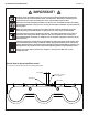
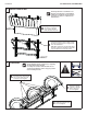
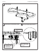
Connect Supply and Tubing
Sprayhead Components
Reinstall the valve bracket. Turn on the water supply to the Express
®
and check for leaks. Push the operating buttons of each
station until all the air is purged from the lines and water is flowing smoothly. Reinstall the access panel.
C
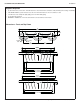
Push Button Assembly
• To access push button assembly: Remove the Phillips-head screws located in the bottom of the sprayhead body and lift
the Terreon cover/shelf off.
• To reinstall sprayhead cover/shelf: Position the cover/shelf on the sprayhead body and secure it to the sprayhead body
using the screws provided.
Loosen the compression nuts.
Push the sprayhead supply tubes firmly
into the tube connectors until they are fully
seated.
Tighten the compression nuts by hand.
A
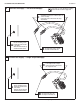
Loosen the compression nuts.
Push the matching color 1/8" tubes firmly
into the tube connectors until they are fully
seated.
Tighten the compression nuts by hand.
B