
Installation / Operation Instruction Manual

5
SECTION II: SPECIFICATIONS
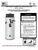
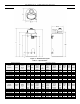
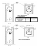
Figure 1 – Dimensional Layout
Table 1 – Specifications
Model Description
Dimensions (inches)
Model
Number
Capacity
(Gal.)
Input
BTU/Hr
Nat. &
L.P.
A
Floor
to Top
of
Vent
B
Vent
Dia.
C
Floor to
Cold
Water
Conn.
D
Floor
to
T&P
E
Floor to
Hot
Water
Conn.
F
Floor to
Top of
Water
Heater
G
Floor
to
Gas
Conn.
Water
Conn.
Dia.
Gas
Conn.
Dia.
Relief
Valve
UCG100H199
100
199,999
73 ¼
6
10
52 ½
55 ½
69 ¾
63 ¾
1 ½
¾
¾
UCG100H270
100
270,000
73 ¼
6
10
52 ½
55 ½
69 ¾
63 ¼
1 ½
¾
1
UCG100H399
98
399,999
77 ¼
8
10
52 ½
55 ½
69 ¾
63 ¼
1 ½
¾
1
UCG80H125
80
125,000
63
5
10
44
47
61 ¼
55 ¾
1 ½
¾
¾
UCG80H199
80
199,000
64 ¾
6
10
44
47
61 ¼
55 ¾
1 ½
¾
¾
UCG80H270
80
270,000
64 ¾
6
10
44
47
61 ¼
55 ¾
1 ½
¾
1
UCG80H399
80
399,999
68 ¾
8
10
44
47
61 ¼
55 ¾
1 ½
¾
1
Model Description
Dimensions (millimeters)
Model
Number
Capacity
(Liters)
Input
kW/Hr
Nat. &
L.P.
A
Floor
to Top
of
Vent
B
Vent
Dia.
C
Floor to
Cold
Water
Conn.
D
Floor
to
T&P
E
Floor to
Hot
Water
Conn.
F
Floor to
Top of
Water
Heater
G
Floor
to
Gas
Conn.
Water
Conn.
Dia.
Gas
Conn.
Dia.
Relief
Valve
UCG100H199
379
58.6
1861
152
254
1334
1410
1772
1607
38
19
19
UCG100H270
379
79.1
1861
152
254
1334
1410
1772
1607
38
19
25
UCG100H399
371
117.2
1962
203
254
1334
1410
1772
1607
38
19
25
UCG80H125
303
36.6
1600
127
254
1118
1194
1556
1391
38
19
19
UCG80H199
303
58.6
1899
152
254
1118
1194
1556
1391
38
19
19
UCG80H270
303
79.1
1899
152
254
1118
1194
1556
1391
38
19
25
UCG80H399
303
117.2
2000
203
254
1118
1194
1556
1391
38
19
25