™ Atmospheric ECO-MAGNUM SERIES Ultra Low NOx Gas Water Heaters SERVICE MANUAL Troubleshooting Guide and Instructions for Service (To be performed ONLY by qualified service providers) Models Covered by This Manual: U175S*RN U2XR75S*RN U100T*RN U75T80R*N U100T88R*N (*) Denotes Warranty Years Manual 238-50628-00A Save this manual for future reference
The Bradford White Atmospheric ECO-MAGNUM Ultra Low NOx Gas Water Heaters Table of Contents Page Service Procedure Introduction 4 --- Tools Required for Service 4 --- Gas Control Troubleshooting Chart 5 --- Burner and Inner Door Gasket Removal, Inspection, Replacement and Installation 7 I Thermopile Testing and Replacement 10 II Pilot Assembly Inspection, Cleaning and Replacement 12 III Igniter and Electrode Testing and Replacement 13 IV Honeywell Gas Control Testing and Replacement
ECO-MAGNUM 75/100-Gallon Atmospheric WARNING If the information in these instructions is not followed exactly, a fire or explosion may result causing property damage, personal injury, or death. FOR YOUR SAFETY Do not store or use gasoline or other flammable, combustible, or corrosive vapors and liquids in the vicinity of this or any other appliance. WHAT TO DO IF YOU SMELL GAS Do not try to light any appliance. x Do not touch any electrical switch; do not use any phone in your building.
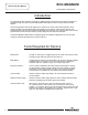
ECO-MAGNUM How to Use This Manual 75/100-Gallon Atmospheric Introduction It is intended for this manual to be used by qualified service personnel for the primary purpose of troubleshooting and repair of the Bradford White Atmospheric Ultra Low NOx Series of water heaters. The Honeywell Gas Control will display error codes in the event of abnormal operation. Error codes are listed in the troubleshooting chart beginning on page 5 of this service manual.
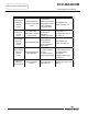
ECO-MAGNUM Gas Control Troubleshooting 75/100-Gallon Atmospheric Observe green LED indicator on gas control. Error flash codes are displayed with a three second pause before repeating. Check and repair the system as noted in the troubleshooting table below. LED Status Control Status None (LED not on or flashing) Gas valve is not powered. One flash and three second pause. 1. If set point knob is in "PILOT" position then pilot flame is detected. Turn set point knob to desired setting 2.
ECO-MAGNUM Gas Control Troubleshooting 75/100-Gallon Atmospheric LED Status Control Status Three flashes and three second pause. Insufficient water heating. System will reset. Four flashes and three second pause. Five flashes and three second pause. Page 6 6 Probable Cause 1. Thermowell sensor and chamber 1&2. Replace gas temperature sensor control, see page 15. out of calibration. 2. Possible short. 1. Thermowell Excessive tank sensor out of temperature. System calibration. must be reset. 2.
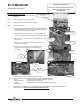
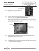
SERVICE PROCEDURE I ECO-MAGNUM Burner and Inner Door/Gasket Removal, Inspection, Replacement and Reinstallation 75/100-Gallon Atmospheric Inner Door Removal Procedure Step 1. Rotate the gas control knob to the “OFF” position. Gas Control Knob Shown In “OFF” Position Step 2. Remove outer jacket burner access door. Step 3. Remove wire clip from main burner feedline. Step 4. Inner Door Removal. 1 a) Disconnect red thermopile lead and red gas control lead from resettable thermal switch.
SERVICE PROCEDURE I Burner and Inner Door/Gasket Removal, Inspection, Replacement and Reinstallation ECO-MAGNUM 75/100-Gallon Atmospheric Inner Door Gasket Replacement Procedure WARNING If the information in these instructions is not followed exactly, a fire or explosion may result causing property damage, personal injury or death. Step 6. After inspection of inner door as noted in step 5, completely remove gasket and adhesive residue from burner door and right side inner door as needed. Step 7.
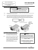
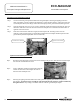
SERVICE PROCEDURE I ECO-MAGNUM Burner and Inner Door/Gasket Removal, Inspection, Replacement and Reinstallation 75/100-Gallon Atmospheric 6 Position Thermopile Wire, Pilot Tube and Igniter Wire Step 10. Position thermopile wires, pilot tube and igniter wire against burner door flange gasket (see photo 6). Step 11. Firmly place right side inner door flange against the burner door flange and secure with two ¼” drive screws from step 4d (see photo 7). DO NOT OVER TIGHTEN SCREWS. Step 12.
ECO-MAGNUM SERVICE PROCEDURE II Thermopile Testing and Replacement 75/100-Gallon Atmospheric Closed Circuit Thermopile Testing Step 1. Closed circuit testing is the preferred method for testing thermopile. Following the lighting instruction label on the heater, proceed to light the pilot and allow to operate for three minutes. If the pilot will not stay lit, hold the pilot button (rotate the gas control knob to the pilot position, push and hold in) during this test. Step 2.
ECO-MAGNUM SERVICE PROCEDURE II Thermopile Testing and Replacement 75/100-Gallon Atmospheric Thermopile Replacement Step 1. Turn off gas supply to water heater. Rotate gas control knob to the “OFF” position. Step 2. Remove outer jacket door. Step 3. Remove right side inner door and burner door per SERVICE PROCEDURE I, steps 3 and 4. Step 4 Follow the thermopile leads to the pilot bracket. Disconnect the thermopile from the pilot bracket (7/16" wrench). Step 5.
SERVICE PROCEDURE III ECO-MAGNUM Pilot Assembly Inspection, Cleaning and Replacement 75/100-Gallon Atmospheric Pilot/Electrode Assembly Inspection, Cleaning and Replacement Gas Control shown in the “OFF” position Step 1. Turn off gas supply to water heater. Rotate gas control knob to the “OFF” position. Step 2. Remove outer jacket door. Step 3. Remove burner and right side of inner door per SERVICE PROCEDURE I, steps 3 and 4. Step 4. Remove burner assembly from combustion chamber. Step 5.
ECO-MAGNUM SERVICE PROCEDURE IV 75/100-Gallon Atmospheric Igniter and Electrode Testing and Replacement Igniter and Electrode Testing and Replacement With the pilot not in operation (no pilot flame) you can check the igniter and electrode circuit by viewing pilot thru the sight glass located on the inner door and observing the spark action. Step 1. Remove outer jacket door. Step 2. Repeatedly depress the igniter button while viewing the pilot thru the sight glass.
ECO-MAGNUM SERVICE PROCEDURE V Gas Control Testing and Replacement 75/100-Gallon Atmospheric Manifold Pressure Testing (this procedure presumes a maximum line pressure of 14.0" w.c.) Step 1. Set the Gas Control to the “OFF” position. Step 2. Remove pressure tap plug and install 1/8" NPT pipe, coupling, & pressure tap. Step 3. Connect manometer to pressure tap. Step 4. Follow instructions located on the lighting instructions label and proceed to light the main burner and observe manometer reading.
ECO-MAGNUM SERVICE PROCEDURE V Gas Control Testing and Replacement 75/100-Gallon Atmospheric Gas Control Replacement Step 1. Rotate knob of the gas control to the “OFF” position. Step 2. Turn off gas supply to water heater. Step 3. Disconnect gas supply line from gas control. Step 4. Turn off water supply and drain water heater completely. Step 5. Remove the wire clip from the feedline. Gas Control shown in the “OFF” position Step 6.
SERVICE PROCEDURE VI Burner Operation Inspection, Cleaning and Replacement ECO-MAGNUM 75/100-Gallon Atmospheric Main Burner Inspection, Cleaning and Replacement At periodic intervals (not more then 6 months) a visual inspection should be made of the main burner for proper operation and to insure no debris is accumulating. Main burner should light smoothly from pilot and burn with a blue flame with a minimum of yellow tips.
ECO-MAGNUM 75/100-Gallon Atmospheric SERVICE PROCEDURE VI Burner Operation Inspection, Cleaning and Replacement Burner Cleaning (Continued) Step 4. Thoroughly inspect burner screen and burner venturis and remove any loose debris accumulation. Inspect burner screen for any openings larger than the normal screen openings. Step 5. Use compressed air and/or a vacuum to remove any scale or other debris accumulation from the burner screen and venturis.
ECO-MAGNUM SERVICE PROCEDURE VII Resettable Thermal Switch Testing and Replacement 75/100-Gallon Atmospheric Resettable Thermal Switch Continuity Testing Step 1. Remove outer jacket door. Step 2. Disconnect red wire leads from resettable thermal switch. Red Wire Leads Step 3. Using a multimeter capable of measuring continuity (Ohms), place one probe of meter on one of the brass connection tabs of the resettable thermal switch, and the remaining probe on the other connection tab. Step 4.
SERVICE PROCEDURE VII ECO-MAGNUM Resettable Thermal Switch Testing and Replacement 75/100-Gallon Atmospheric Resettable Thermal Switch Replacement Step 1. Rotate gas control knob to the “OFF” position. Step 2. Remove outer jacket door. Step 3. Disconnect red wire leads from resettable thermal switch. Gas Control shown in the “OFF” position ¼” Hex Drive Manifold Cover Screws Step 4. Remove (2) ¼” hex drive screws from the manifold cover and slid to the right to remove from burner assembly.
SERVICE PROCEDURE VIII Dip Tube and Anode Inspection and Replacement ECO-MAGNUM 75/100-Gallon Atmospheric Dip Tube Inspection and Replacement WARNING Water Heater components and stored water may be HOT when performing the following steps in this procedure. Take necessary precaution to prevent personal injury. Step 1. Rotate gas control knob to the “OFF” position. Gas Control shown in the “OFF” position Step 2. Turn off cold water supply to water heater.
ECO-MAGNUM 75/100-Gallon Atmospheric SERVICE PROCEDURE VIII Dip Tube and Anode Inspection and Replacement Anode Inspection and Replacement WARNING Heater components and stored water may be HOT when performing the following steps in this procedure. Take necessary precaution to prevent personal injury. Step 1. Rotate gas control knob to the “OFF” position. Gas Control shown in the “OFF” position Step 2. Turn off cold water supply to heater.
ECO-MAGNUM Glossary of Terms 75/100-Gallon Atmospheric BTU GPM Hz KWh LED NPT Ohms PSI RPM ECO VAC VDC W.C.
ECO-MAGNUM Parts List 75/100-Gallon Atmospheric 75-Gallon Models 1 2 3 4 5 6 7 8 9 10 11 12 13 Draft Diverter Flue Baffle Anode Cold Water Inlet Tube Hot Water Outlet Nipple T&P Releif Valve Space Heating Plug Gas Valve Brass Drain Valve Outer Door RN Burner and Door RN Burner Flexible Gas Feedline 14 15 16 17 18 19 20 21 22 23 24 25 26 Screw #6-20 x 3/8" Resettable Thermal Switch Manifold Cover Screw #8-18 x ¾” Manifold bracket Right Side Inner Door Screw #10-12 x ¾ ASSE Approved Mixing Valve (Option
ECO-MAGNUM Parts List 75/100-Gallon Atmospheric 100-Gallon Models 1 2 3 4 5 6 7 8 9 10 11 12 13 Draft Diverter Flue Core Anode Cold Water Inlet Tube Hot Water Outlet Nipple T&P Releif Valve Space Heating Plug Gas Valve Brass Drain Valve Outer Door RN Burner and Door RN Burner Flexible Gas Feedline 14 15 16 17 18 19 20 21 22 23 24 25 26 Screw #6-20 x 3/8" Resettable Thermal Switch Manifold Cover Screw #8-18 x ¾” Manifold bracket Right Side Inner Door Screw #10-12 x ¾ ASSE Approved Mixing Valve (Optional)
NOTES Page 23 25
NOTES Page 23 26
NOTES Page 23 27