
Installation / Operation Instruction Manual


13
SECTION V: VENTING
This water heater has been shipped with a draft hood for which it was designed with reference to the horizontal and
vertical planes. If removed, the draft diverter must be replaced in the same position and secured to the jacket top by the
screws with which it was installed.
This water heater must be connected to a lined masonry chimney or venting system approved by local codes or
ordinances. The vent connector used to attach the draft hood outlet to the chimney or approved vent must be of the same
diameter as the draft diverter outlet or larger. For proper venting in certain installations, a larger vent connector may be
needed. Consult venting tables in ANSI standard (Z223.1- latest edition), National Fuel Gas Code and CAN/CGA
(B149.1 or B149.2-latest editions) Natural Gas and Propane Installation Code, or local code officials for proper application
for your area.
This water heater is equipped with a condensate relief opening to allow excessive flue gas condensate to drain from the
water heater/vent system and prevent accumulation of flue gas condensate. Under normal operation, condensate will not
drain from the relief opening continuously. However, minor, sporadic drainage may occur during initial cold start-up or
excessive usage patterns.
Very low flue gas temperatures caused by under-sizing the water heater for the application, improper input rate, low water
temperature set-point, excessively cold water temperatures and/or other adverse local conditions will cause flue gas
condensate to continuously form in the water heater and drain from the condensate relief opening. Flue gas condensate
is highly acidic and will degrade/damage materials over time. Damage to the water heater and surrounding areas will
occur if the condensation is allowed to occur on a long term or extended basis.
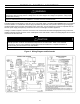
SECTION VI: WATER CONNECTIONS
The venting system must be installed properly following all local codes or in the absence of local codes, the latest
edition of the National Fuel Gas Code (ANSI Z223.1- latest edition), or in Canada, The Natural Gas Installation
Code (B149.1-00 latest edition). Failure to properly install the venting system could result in property damage,
personal injury, or death.
Carefully inspect the venting system of a replacement water heater installation before connecting to the venting
system. All joints in the vent connector must be securely fastened with screws and fit tightly together. Inspect the
venting system for signs of deterioration (rust and perforation) and replace any sections that are not in good
condition.
The chimney must be lined and in good condition. Check to make sure the venting system is properly sized for the
water heater. If the venting system was previously sized for another gas appliance that has been removed, the
venting system may now be too large. Refer to the latest edition of the National Fuel Gas Code (ANSI Z223.1-latest
edition), or in Canada, the Natural Gas and Propane Installation Code (B149.1-00 latest edition) for the correct
sizing of venting systems and common venting with another gas appliance. Do not vent this water heater into the
venting system of another gas appliance designed to vent under positive pressure.
The water heater should be installed as close as practical to the venting system to minimize the vent connector
length required. Refer to local codes for the distance limitations on vent connector lengths. At the completion of the
water heater installation, the burner and venting system must be checked for proper operation with all other
commonly vented appliances in operation. Check for spillage of flue products around the outside relief opening of
the drafthood after several minutes of operation. The flame from a match should be drawn into the drafthood. Do
not use the water heater or connected equipment if spillage is detected until the problem is corrected. Refer to the
latest edition of the National Fuel Gas Code, or in Canada, the Natural Gas and Propane Installation Code for
complete details on the “Procedure to Be Followed to Place Equipment in Operation”.
WARNING
DONOTblockorrestrictcondensatereliefopening.Thisopeningmustremainopenandclearofobstructionsatalltimes.
DONOToperatethewaterheaterwithfluecondensatecontinuouslyflowingfromthecondensatereliefopeningona
longtermorextendedbasis
WARNING