
Service Manual


Step 1. Position main power switch to “OFF”.
Step 2. Disconnect (unplug) water heater from
120 volt power source.
Step 3. Turn off gas supply to water he
ater.
Step 4. Un-latch & remove surround cover from top of
heater.
Step 5.From the gas valve, disconnect the gas
connection, PVC damper assembly, silicone tubin
g
and wire harness.
Step 6. Disconnect wire harnesses to the flame sensor,
spark rod connection, blower, damper, circulator,
flow switch, blocked vent switch and
thermostat
sensor.
Step 7. Remove screws that hold jacket head onto the
jacket.
Step 8. Remove jacket head with all control panel and all
the wi
re harnesses attached to it.
Step 9. Remove the two pieces of insulation that cover
access to the burner mounting insert.
Step 10. Remove the 4 screws (philips head) that ho
ld the
Spark Rod and Flame Sensor.
Step 11. Remove the Spark Rod and Flame Sensor. The
gaskets will need to be replace when reinstalled.
Step 12.
Remove the 6 nuts (7/16" socket) holding the
burner plate and combustion system in place.
Step 13. Remover combustion system and burner plate f
rom
the mounting assembly. See next page for burner
tube installation procedure.
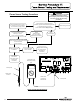
Burner Tube Removal Procedure
WARNING
120 volt potential exposure. Isolate the
appliance and reconfirm power is
disconnected using a multi-meter.
WARNING
Heater components may be HOT when performing the following steps in this procedure.
Take necessary precaution to prevent personal injury.
35
Spark Rod and Flame
Sense
Combustion system
and burner plate
Burner
Burner Gasket (X2)
Remove 6 nuts
(7/16" socket)
Mounting Assembly
35