GAS-FIRED COMMERCIAL WATER HEATER (Ultra Low NOx) WARNING: If the information in these instructions is not followed exactly, a fire or explosion may result causing property damage, personal injury or death. - Do not store or use gasoline or other flammable vapors and liquids in the vicinity of this or any other appliance. - WHAT TO DO IF YOU SMELL GAS Do not try to light any appliance. Do not touch any electrical switch; do not use any phone in your building.
SECTION I: IMPORTANT INFORMATION READ CAREFULLY This gas-fired water heater is design certified by CSA International under the American National Standard, Z21.10.3 and CAN/CGA 4.3-M (as indicated on the rating plate). These standards are available from CSA Standards Association, 5060 Spectrum Way Mississauga, Ontario L4W 5N6 CANADA. This water heater must be installed in accordance with local codes. In the absence of local codes, it must be installed in compliance with the National Fuel Gas Code (ANSI Z223.
DANGER DO NOT store or use gasoline or other flammable, combustible, or corrosive vapors and/or liquids in the vicinity of this or any other appliance. This water heater is equipped with an adjustable thermostat to control water temperature. Hot water temperatures required for automatic dishwasher and laundry use can cause scald burns resulting in serious personal injury and/or death. The temperature at which injury occurs varies with the person’s age and the time of exposure.
WARNING This water heater needs fresh air for safe operation and must be installed so there are provisions for adequate combustion and ventilation air. Insufficient air supply will cause a recirculation of combustion products resulting in contamination that may be hazardous to life. This will result in carboning or sooting of the combustion chamber, burner, and flue tubes and creates a risk of asphyxiation.
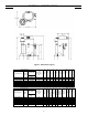
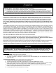
SECTION II: SPECIFICATIONS Figure 1. Dimensional Layout Model Description Model Number Capacity (GAL) U65L155E3N(A) U65L199E3N(A) U65L270E3N(A) U100L199E3N(A) U100L270E3N(A) U100L300E3N(A) U100L399E3N(A) 65 65 65 100 100 100 100 Input BTU/Hr. NAT. 155,000 199,999 270,000 199,999 270,000 300,000 399,999 1st Hour Delivery at 100°F Rise (Gal.
SECTION III: GENERAL INFORMATION FEATURES This water heater contains the following features: MAIN POWER ON/OFF SWITCH – The front panel of this water heater has a lighted ON/OFF switch, which is illuminated when the main power is turned on to indicate power to the water heater. COMBUSTION SYSTEM – This water heater is equipped with a self-compensating negative pressure pre-mix combustion system.
WARNING Keep clear of combination temperature and pressure relief valve discharge line outlet. The discharge may be hot enough to cause scald injury. The water is under pressure and may splash.
SECTION IV: INSTALLATION INSTRUCTIONS WARNING INSTALLATION OF THIS WATER HEATER REQUIRES ABILITY EQUIVALENT TO THAT OF A LICENSED TRADESPERSON IN THE FIELD INVOLVED. PLUMBING, AIR SUPPLY, VENTING, GAS SUPPLY AND ELECTRICAL WORK ARE REQUIRED. DO NOT ATTEMPT TO LIGHT ANY GAS APPLIANCE IF YOU ARE NOT CERTAIN OF THE FOLLOWING: Liquefied petroleum gases/propane gas and natural gas have an odorant added by the gas supplier that aids in detection of the gas.
CAUTION The National Fuel Gas Code (ANSI Z233.1- latest edition) or in Canada The Natural Gas Installation Code CAN/CGA (B149.1 - latest edition), expressly prohibits the following: a. Installation of a water heater in a bathroom, bedroom, or any occupied room normally kept closed. b. Installation of a water heater in a garage, unless the unit is installed so that the burner and ignition devices are at least eighteen (18) inches (45.8 cm) above floor level and protected to avoid damage by a moving vehicle.
Input Front, sides and Rear “A” Less than or equal to 399,999 BTUH 0 in. (0.0 CM) Figure 2a. Minimum Clearance To Combustible Material Figure 2b.
REMOVE CRATE 1. Remove all banding and pry off crate sides carefully so as not to damage the water heater. 2. Carefully roll/lift the water heater from the crate base. CAUTION Do not drop water heater. Do not bump water heater jacket against floor. Do not bump exhaust vent pipe against crate or other objects. This will damage the heater and cause it to be inoperable or create nuisance problems. MOVE WATER HEATER TO PERMANENT POSITION by sliding or walking.
CAUTION The draft hood relief opening of the water heater and combustion air inlet must be in the same atmospheric pressure zone. Large exhaust fans in kitchens and other locations can lower the air pressure inside an enclosure and interfere with the proper operation and venting of the water heater. In these cases, the water heater should be installed in a separate room with the combustion and ventilation air supplied directly from outdoors as previously described. 1.
SECTION V: VENTING WARNING The venting system must be installed properly following all local codes or in the absence of local codes, the latest edition of the National Fuel Gas Code (ANSI Z223.1- latest edition), or in Canada, The Natural Gas Installation Code (B149.1-00 latest edition). Failure to properly install the venting system could result in property damage, personal injury, or death.
SECTION VI: WATER CONNECTIONS NOTE: BEFORE PROCEEDING WITH THE INSTALLATION, CLOSE THE MAIN WATER SUPPLY VALVE. After shutting off the main water supply, open a faucet to relieve the water line pressure to prevent any water from leaking out of the pipes while making the water connections to the water heater. After the pressure has been relieved, close the faucet. The COLD water inlet and HOT water outlet are identified on the front of the water heater.
WARNING Keep clear of combination temperature and pressure relief valve discharge line outlet. The discharge may be hot enough to cause scald injury. The water is under pressure and may splash.
SECTION VII: GAS CONNECTIONS The gas supply lines must meet all requirements of the National Fuel Gas Code (ANSI Z223.1-Latest Edition), or in Canada CAN/CGA B149.1 Natural Gas Installation Code (Latest Edition). The minimum permissible gas supply pressure for the purpose of input adjustment is one (1.0) inch (0.25 kPa) water column above the operating manifold pressure. See the rating plate and gas valve for the manifold pressure. The maximum permissible gas supply pressure is fourteen (14.0) inches (3.
WARNING Water heaters are heat-producing appliances. To avoid damage or injury there must be no materials stored against the water heater or direct vent system, and proper care must be taken to avoid unnecessary contact (especially by children) with the water heater and direct vent system. UNDER NO CIRCUMSTANCES SHOULD FLAMMABLE MATERIALS, SUCH AS GASOLINE OR PAINT THINNER BE USED OR STORED IN THE VICINITY OF THIS WATER HEATER OR IN ANY LOCATION FROM WHICH FUMES COULD REACH THE WATER HEATER.
SECTION VIII: ELECTRICAL CONNECTIONS WARNING Turn off or disconnect the electrical power supply to the water heater before servicing. Label all wires prior to disconnection when servicing controls. Wiring errors can cause improper and dangerous operation. Verify proper operation after servicing. All electrical wiring must be installed and grounded in accordance with local codes, or in the absence of local codes, the National Electrical Code, ANSI/NFPA 70 and/or CSA C22.2 Electrical Code.
SECTION IX: OPERATING INSTRUCTIONS Lighting And Shutdown Instructions WARNING Water heaters are heat-producing appliances. To avoid damage or injury there must be no materials stored against the water heater or vent system, and proper care must be taken to avoid unnecessary contact (especially by children) with the water heater and vent system.
LIGHTING AND SHUT-DOWN INSTRUCTIONS Figure 4. Lighting Instruction Label TEMPERATURE ADJUSTMENT APPROXIMATE TIME/TEMPERATURE RELATIONSHIPS IN SCALDS 120°F (49°C) More than 5 minutes 125°F (52°C) 1½ to 2 minutes 130°F (54°C) About 30 seconds 135°F (57°C) About 10 seconds 140°F (60°C) Less than 5 seconds 145°F (63°C) Less than 3 seconds 150°F (66°C) About 1½ seconds 155°F (68°C) About 1 second Table 3.
DANGER Hotter water increases the risk of scald injury. Scalding may occur within five (5) seconds at a temperature setting of 140F (60C). To protect against hot water injury, install an ASSE approved mixing valve in the water system. This valve will reduce point of discharge temperature by mixing cold and hot water in branch water lines. A licensed plumbing professional or local plumbing authority should be consulted. This water heater is equipped with an energy cut out device to prevent overheating.
TEMPERATURE ADJUSTMENT (24V CONTROL SYSTEM) The water heater temperature setting is adjusted by using the control display mounted to the front of the water heater. The water heater thermostat is set at the lowest setpoint of 70F when shipped from the factory. The control display shows the temperature setpoint in degrees Fahrenheit (F) or degrees Celsius (C), and the status of the water heater (“Idle” or “Heating”). If the water heater is functioning normally, the display will also show “Operational”.
Shown flashing in display only when temp is adjusted Water Heater Display and Control Buttons Sequence of operation Indicator Reads "Idle” or “Heating" Status Indicator Read "Operational" or "Service Needed" Temperature Up Button °F setpoint idle Status Operational SELECT SET Temperature Setpoint in Degrees F or Degrees C Range 70 - Max °F Range 21 - Max °C Temperature Down Button Set button Select button To Increase Setpoint Temperature Step 1: Depress and hold “Temperature Up” button until desir
Step 3: Press “SET” button for new setting to take effect immediately. “Setpoint” will stop flashing. If the “SET” button is not pressed, the new temperature setting will take effect in approximately 10 seconds.
Step 3: Press “SET” button for new setting to take effect immediately. The setpoint will stop flashing. If the “SET” button is not pressed, the new temperature setting will take effect in approximately 10 seconds. "Setpoint" flashes for 10 seconds setpoint °F idle Status Operational SELECT SET Step 3 Press SET for setting to take effect immediately To Change Temperature Format in Display from F to C or ˚C to ˚F: Step 1: Press “SELECT” button until F/C is displayed.
Step 3a: Press “Temperature Up” button to change temperature format to C. Changes to "°C" °C °F/°C idle Status Operational SELECT SET °F/°C Flashes Step 3a Step 3b: Press “Temperature Down” button to change temperature format to F. Changes to "°F" °F/°C Flashes °F °F/°C idle Status Operational SELECT SET Step 3b Step 4: Press “SET” button to confirm ˚F or ˚C format. F/C will stop flashing. Setpoint display will appear in the format selected (˚F or ˚C) in 10 seconds.
Step 5: Pressing “SELECT” button will return display to setpoint in format selected (˚F or ˚C) immediately. Setpoint shown in °F °F idle Status Operational SELECT SET Press select Step 5 An automatic gas shut-off device (ECO) is incorporated in the sensor and control board which will shut off all gas supply to the burner if the water heater temperature exceeds 200°F (93°C).
SECTION X: MAINTENANCE DANGER DO NOT ATTEMPT TO REPAIR GAS VALVE. DO NOT ATTEMPT TO REPAIR IGNITION MODULE. DO NOT ATTEMPT TO REPAIR VENTURI. DO NOT ATTEMPT TO REPAIR THERMOSTAT BOARD. DO NOT ATTEMPT TO REPAIR TRANSFORMER. DO NOT ATTEMPT TO REPAIR FLOW SWITCH. GENERAL KEEP APPLIANCE AREA CLEAR AND FREE FROM COMBUSTIBLE MATERIALS, GASOLINE AND OTHER FLAMMABLE VAPORS AND LIQUIDS. Water heater maintenance includes periodic tank flushing and cleaning, and removal of lime scale.
MAINTENANCE SCHEDULE Following are the instructions for performing some of the recommended maintenance. Unit inspection and adjustment should be performed by a competent technician.
The usage of water softening equipment greatly reduces the hardness of the water. However, this equipment does not always remove all of the hardness (lime). For this reason it is recommended that a regular schedule of deliming be maintained. The depth of the buildup should be measured periodically. Water heaters will have about 3 inches of lime buildup when the level of lime has reached the bottom of the cleanout opening or about 1 inch of lime buildup if it has reached the drain valve opening.
DRAIN VALVE AND TANK ACCESS PANEL The water heaters are equipped with a ¾ inch drain valve. An access panel covers the cleanout opening in the tank, which is sealed by a gasket and cover. RELIEF VALVE At least twice a year, the temperature and pressure relief valve should be checked to ensure that it is in operating condition. To check the relief valve, lift the lever at the end of the valve several times. The valve should seat properly and operate freely.
SECTION XI: DIAGNOSTIC AND TROUBLESHOOTING GUIDE DIRECT SPARK HONEYWELL INTEGRATED CONTROL SYSTEM SEQUENCE OF OPERATION 1. When the tank temperature drops below the temperature setpoint on the display, the control sends power to the combustion blower for a 30 second pre-purge period, circulator turns on and damper opens. 2. At the end of the pre-purge period, the control sends high voltage through the spark cable to the spark rod to spark to the burner. The gas valve also opens.
Step 1: Press “Select” and “Temperature Up” buttons together and hold for 3 seconds until “Max Setpoint” is shown in the display. “Max Setpoint” next to Temperature Setpoint value. Max Setpoint °F idle Status Operational SELECT SET NOTICE Approximately 12 minutes after the last button press, the display will automatically return to the “User Mode”. Simultaneously pressing the “Select” and “Temperature Up” buttons will switch the display immediately to the “User Mode”.
1. Max Setpoint (Display/Change) Max Setpoint value in Water Heater Display Max Setpoint °F idle Status Operational SET SELECT 2. Water Temperature Sensor Reading. °F Water Temp idle Status Operational SET SELECT 3.
4. Setpoint (Display/Change) setpoint °F idle Status Operational SET SELECT 5. ˚F/˚C (Display/Change) °F °F/°C idle Status Operational SET SELECT 6.
7. Software Version (Display only) Soft idle Status Operational SELECT SET 8. Error Code History (Displays if there are present error codes or up to 10 previous error codes). Water Heater Display will show -- if there are no error codes.
To change the Maximum Setpoint Limit (Max Setpoint) for the temperature setpoint: WARNING Setting the water temperature to the maximum set point can result in scalding hot water delivered to the faucets. It is highly recommended that the maximum setpoint be adjusted to the lowest temperature possible for the needs of the installation. See following section to change the maximum setpoint limit (max setpoint).
Step 3: Press the “UP” or “DOWN” buttons to change the maximum setpoint value. This will limit the maximum setpoint the user can select. Note: The maximum setpoint is approximately 180˚F (82˚C). "Max Setpoint" continues to flash while making adjustments °F Max Setpoint idle Status Operational SET SELECT Step 4: Press “Set” button to confirm new “Max Setpoint” value and stop setting mode.
Display of Water Temperature: Step 1: In Service Mode, Press the “Select” button until “Water Temp” is displayed in the upper right section of the water heater display. This is the reading for the tank sensor. Water Temp °F idle Status Operational SET SELECT To Display Flame Sense Current of the Pilot Flame Sensor: The pilot flame sense current is available only when the burners are in operation. Step 1: Make sure the status displays “Heating” or draw enough hot water to start the burners.
To Display and Change Temperature Setpoint: Step 1: In “Service Mode” press the “Select” button until “Setpoint” is shown in the water heater display. setpoint °F idle Status Operational SET SELECT Step 2: Press the “Set” button to enter the setting mode. “Setpoint” will flash in the water heater display.
Step 4: To lower the temperature setpoint, press the “Temperature Down” button until the desired temperature is shown on the water heater display. "Setpoint" Flashes °F setpoint idle Status Operational SELECT SET Step 5: When the desired setpoint is reached on the water heater display, press the “Set” button to confirm the new setpoint. “Setpoint” stops flashing in the water heater display.
Step 2: Press “Set” button to change temperature format. “˚F/˚C” symbol will flash in the water heater display. "°F/°C" Flashes °F °F/°C idle Status Operational SELECT SET Step 3a: Press “Temperature Up” button to change temperature format to ˚C. Changes to "°C" "°F/°C" Flashes °C °F/°C idle Status Operational SELECT SET Step 3b: Press “Temperature Down” button to change temperature format to ˚F.
Step 4: Press “Set” button to confirm ˚F or ˚C format. ˚F/˚C will stop flashing. "°F/°C" Symbol Stops Flashing °F °F/°C idle Status Operational SELECT SET Step 5: Pressing “Select” button will return display to setpoint in format selected (˚F or ˚C) immediately.
How to reset the control from Lockout Conditions: WARNING The following procedure is for service and installation personnel only. Resetting lockout conditions without correcting the malfunction can result in a hazardous condition. If an error code is displayed (except for #4, low flame sense current), the water heater will be in a “lockout condition” with the water heater display showing the error code number and “Service Needed” in the status section of the display window.
Error Codes and Error History Display: If there is an operating problem with the water heater, an error code number will appear on the water heater display with “Service Needed” to the right of the “Status” indicator. The error code label is located below the water heater display and the following section in this Installation and Operating Instruction Manual explains the error codes with corrective actions to repair the water heater.
Step 2: Press the “Temperature Down” button to select the error code index, starting with the most recent error code “10”. Error Code Index idle Status Operational SET SELECT Step 3: Press the “Select” button to view the error code for “code 10”. If there is a number displayed, note what the number is. The label next to the water heater display will identify the code number.
Step 5: Press the “Select” button for code index #9 to view if there are any code numbers. Stored Error Code For Code Index #9 idle Status Operational SELECT SET Step 6: Continue pressing the “Temperature Down” button to change to the next error code index and press “Select” to view the error code number, if any, for that index number. Continue on to index #1, the oldest error code index.
DIAGNOSTIC ERROR CODES AND TROUBLESHOOTING PROCEDURES FOR EF MODELS WITH HONEYWELL INTEGRATED DIRECT SPARK IGNITON CONTROL SYSTEM Error Code Definition of Code Cause of Problem and Actions Taken to Correct Check power supply to the water heater. Make sure water heater is plugged in and the breaker is on. Check if there is 120 volts power supply to the LINE connections on the control board. If 120 volts is present, check for 24 volts output to SECONDARY terminals on the Control Board.
Error Code Definition of Code Cause of Problem and Actions Taken to Correct Maximum Number of Retries Detected Burner is either not lighting or not staying lit during ignition cycle. Check inlet gas pressure for minimum pressure on rating label. Can you hear sparking to the burner? Check high voltage cable connections. Check inlet gas pressure to the gas valve making sure the pressure is within the limits specified on the rating label. Check gas valve wire harness for broken wires or shorts.
Procedure for Checking Thermostat Sensors Set the thermostat above water temperature (See temperature adjustment section) and observe system through one (1) complete cycle. Make sure system operates as desired. To check the upper sensor assembly, compare the resistance of the sensor terminals (yellow and black lead for upper sensor) as measured by an ohmmeter to the water temperature as measured by an accurate thermometer. Thermistor resistance increases as the temperature decreases.
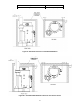
SECTION XII: PARTS LIST U Model – Water Heater 1 Surround Assembly Combustion Assembly 2 (Specify model) 3 Ignition Control Assembly 4 Draft Hood (Specify model) 5 Vent Vertical Tube 6 Vent Protector Assembly 7 Baffle 3” Flue (Specify Model) 8 Damper Bracket (Specify Model) 9 Thermostat Sensor 10 Utility Cover 11 Circulator Assembly 12 ¾” NPT Nipple 13 Stainless Flex Connector 14 NPT/SAE Adapter 15 T&P (Specify Model) 16 Hot Water Outlet Plastisert Nipple 17 Anode 18 Cold Water Inlet (Hydrojet) Assembly 19
2 Combustion Assembly 1 2 3 4 5 6 7 8 9 10 11 12 13 Combustion Assembly (Specify model) Blower/Gas Valve Assembly (Specify model) Burner Assembly (Specify model) Blower – (Specify model) Damper Assembly (Specify Model) Transition Tube Gasket Blower Transition Gasket Transition Tube 1/4 – 20 Nut Screw 8-32 x ¼” RHCR Gasket Flame Sense Gasket Igniter Sensor – Flame Sense 14 Igniter – Direct Spark Ignition 15 16 17 18 19 20 Blower / Burner Mounting Plate Gasket Burner (Specify Model) Burner (Specify Model)
3 Ignition Control Assembly and Harnesses 1 2 3 4 5 6 7 8 9 10 Control Panel Control Transformer Display Panel Screw Switch Main Power Control Display Screw Blower/Circ/Damper Harness (24V) Damper Harness (120V) 11 12 13 14 15 16 17 18 Controller Harness (24V) Power Cord Harness (120V) Blocked Vent Switch Harness (24V) T-Stat Harness (24V) Control Display Harness (24V) Blower Harness (120V) Circ/Flow Harness (120V) BVS/Damper/Flow Harness (24V) 19 Ignition Harness (Direct Spark Ignition) 20 Flame Sen
SECTION XIII: NOTES 54
SECTION XIII: NOTES 55
SECTION XIII: NOTES 56