
Installation / Operation Instruction Manual

11
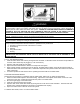
REMOVE CRATE
1. Remove all banding and pry off crate sides carefully so as not to damage the water heater.
2. Carefully roll/lift the water heater from the crate base.
CAUTION
Do not drop water heater. Do not bump water heater jacket against floor.
Do not bump exhaust vent pipe against crate or other objects. This will damage the heater and cause it to be
inoperable or create nuisance problems.
MOVE WATER HEATER TO PERMANENT POSITION by sliding or walking.
INSTALL TEMPERATURE AND PRESSURE RELIEF VALVE (if not already installed).
DANGER
Temperature setting should not exceed safe temperature at fixtures. See water temperature control warning in
Section VI, “Water Connections”. If higher preheat temperatures are necessary to obtain adequate booster output,
add an ASSE approved mixing device for hot water supplied to fixtures.
WARNING
Temperature and pressure relief valve discharge piping must be piped near floor to eliminate potential of severe
burns. Do not pipe in any area where freezing could occur. Do not install any shut-off valves, plugs or caps to the
temperature and pressure relief valve or piping.
This water heater must be located in an area where the general public does not have access to set temperatures.
AIR REQUIREMENTS
1. Do not obstruct the flow of ventilating air.
2. For safe operation, adequate air is needed for combustion and ventilation. Sooting may result in serious damage
to the water heater and risk of fire or explosion. It can also create a risk of asphyxiation. Such a condition often
will result in a yellow, luminous burner flame, causing carboning or sooting of the combustion chamber, burner
and flue tubes.
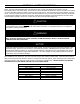
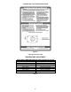
CONFINED SPACES
If the water heater is installed in a confined space (volume is less than 50 ft.
3
/1000 BTU (15 m
3
/0.29 kW) per hour of the
total input rating of all gas appliances in that space), air must be supplied through two permanent openings. One opening
msut be within 12 inches (30.5 cm) from the top of the enclosure and one within 12 inches (30.5 cm) of the bottom. The
openings must be protected by metal louvers or 1/4” (6.4 mm) min. mesh metal screen. The size of the openings are as
follows:
IMPORTANT-The flow of combustion and ventilating air must not be obstructed.
MECHANICAL EXHAUSTING OF ROOM AIR - Where an exhaust fan is installed in the same room with this
water heater and combustion air is drawn from inside the room, sufficient openings for air must be provided in the
walls. UNDERSIZED OPENINGS WILL CAUSE AIR TO BE DRAWN INTO THE ROOM THROUGH THE WATER
HEATER’S VENTING SYSTEM, CAUSING POOR COMBUSTION THAT MAY BE HAZARDOUS TO LIFE.
SOOTING MAY RESULT IN SERIOUS DAMAGE TO THE WATER HEATER AND RISK OF FIRE OR EXPLOSION,
WHICH CAN ALSO CREATE A RISK OF ASPHYXIATION. Refer to local codes and /or National Fuel Gas Code
(ANSI Z223.1-Latest Edition), or in Canada CAN/CGA B149.1 Natural Gas Installation Code (Latest Edition) for
proper air opening sizing.
WARNING