
Installation / Operation Instruction Manual


5
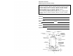
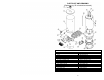
PARTS LIST AND DRAWING
(Replaces pg. 25 in instruction manual)
PART NAME AND DESCRIPTION
1. Draft Diverter 15. Drain Valve
2. Jacket Head Pan 16. Gas Control Valve
3. Jacket 17. Manifold Bracket
4. Outer Door 18. Re-Settable Thermal Switch Wire Harness
5. Nipple-Hot Water Outlet 19. Burner Assembly
6. Flue Core 20. Re-settable Thermal Switch
7. Dip Tube-Cold Water Inlet 21. Burner Assembly Cover
8. Temperature and Pressure Relief Valve 22. Gas Feedline
9. Glass Lined Tank 23. Orifice
10. Heat Radiation Shield 24. Thermopile Wire
11. Foam Insulation 25. Igniter Wire
12. Combustion Chamber Assembly 26. Pilot Gas Feedline
13. Jacket Base Pan 27. Pilot Assembly
14. Inner Door Assembly 28. Heater Leg
14A. #8 x ¾ screw 29. Magnesium Anode-Hex Head