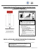
Bradford White EverHot Condensing Tankless Gas Water Heater For Interior Installation TGHE-160I-N(X) & TGHE-199I-N(X) WARNING: If the information in these instructions is not followed exactly, a fire or explosion may result causing property damage, personal injury or death Do not store or use gasoline or other flammable vapors and liquids in the vicinity of this or any other appliance WHAT TO DO IF YOU SMELL GAS Do not try to light any appliance.
SECTION I: IMPORTANT INFORMATION READ CAREFULLY This gas-fired water heater is design certified by CSA International under the American National Standard, Z21.10.3 Latest Edition (as indicated on the rating plate) and CAN/CGA 4.3-M Latest Edition (as indicated on the rating plate) available from CSA Standards Association, 5060 Spectrum Way, Mississauga, Ontario, Canada L4W 5N6. This water heater must be installed in accordance with local codes.
DANGER DO NOT store or use gasoline or other flammable, combustible, or corrosive vapors and/or liquids in the vicinity of this or any other appliance. Failure to properly install the vent and air intake (if applicable) system could result in property damage, personal injury, or death. DO NOT install any damaged venting system components. If damage is evident, please contact the supplier where the water heater was purchased or the venting manufacturer.
WARNING DO NOT tamper with or alter the water heater and/or controls. DO NOT operate water heater with jumpered or absent controls or safety devices. DO NOT operate water heater if any external part has been under water. Immediately call a qualified service technician to inspect the water heater and to replace any part of the control system including gas controls, which has been under water. DO NOT attempt to use this water heater with any gas other than the type listed on the rating plate.
WARNING Liquefied petroleum gases/propane gas is heavier than air and will remain at floor level if there is a leak. Basements, crawl spaces, closets and areas below ground level will serve as pockets for accumulation of leaking gas. Before lighting, smell all around the appliance area for gas. Be sure to smell next to the floor. IF YOU SMELL GAS: DO NOT try to light any appliance. DO NOT touch any electric switch; do not use any telephone in your building.
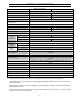
SECTION II: SPECIFICATIONS Table 1. Specifications. Model TGHE-160I-N(X) Minimum Rate Btu/h TGHE-199I-N(X) 9,500 (Natural) / 10,300 (Propane) Maximum Rate Btu/h 157,000 199,000 Flow Rate (Min-Max) * 0.4-8.0 GPM (1.5-30 L/min) 0.4-9.8 GPM (1.5-37 L/min) Flow Rate (45°F rise) 6.6 GPM (25 L/min) 8.
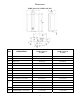
Dimensions TGHE-160I-N(X), TGHE-199I-N(X) Table 2. Water Heater Dimensions (Approx.). DIM DESCRIPTION TGHE-160I-N(X) in. (mm) TGHE-199I-N(X) in. (mm) 18 ½ (470) 18 ½ (470) A Width B Depth * 10 ½ (266.9) 10 ½ (266.9) C Height - Unit 26 3/8 (670) 26 3/8 (670) D Height - with brackets 28 ½ (723.2) 28 ½ (723.2) E Hot Water Outlet - from wall * 4 ¼ (110) 4 ¼ (110) F Hot Water Outlet - from center 3 7/8 (100) 3 7/8 (100) G Cold Water Inlet - from wall * 2 ¾ (70.0) 2 ¾ (74.
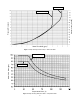
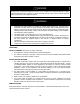
TGHE-199I-N(X) Pressure Drop (psi) Pressure Loss (ft head) TGHE-160I-N(X) Water Flow Rate (gpm) Figure 1. Graph Showing Pressure Drop v. Water Flow Rate. Water Flow Rate (gpm) TGHE-199I-N(X) TGHE-160I-N(X) Temperature Rise (°F) Figure 2. Graph Showing Water Flow Rate v. Temperature Rise.
SECTION III: INSTALLATION INSTRUCTIONS WARNING INSTALLATION OF THIS WATER HEATER REQUIRES ABILITY EQUIVALENT TO THAT OF A LICENSED PLUMBER. Plumbing, air supply, venting, gas supply and electrical work are required. DO NOT ATTEMPT TO LIGHT ANY GAS APPLIANCE IF YOU ARE NOT CERTAIN OF THE FOLLOWING: Liquefied petroleum gases/propane gas and natural gas have an odorant added by the gas supplier that aids in detection of the gas. Most people recognize this odor as a “sulfur” or “rotten egg” smell.
DANGER Temperature setting should not exceed safe temperature at fixtures. See water temperature control warning in the “Temperature Adjustment” section of this Installation and Operation Manual. If higher preheat temperatures are necessary to obtain adequate booster output, add an ASSE approved mixing valve for hot water supplied to fixtures. WARNING Residential use water heaters are suitable for potable water heating only.
MOUNT WATER HEATER ON THE WALL Determine the proper height and location for the water heater to be installed. Consider the venting system, as well as the water and gas connections. Allow enough room for servicing the water heater and maintain the clearances from combustible materials. The water heater is supported on the wall by means of a top and bottom slotted angle bracket.
State Regulations NOTICE BEFORE INSTALLATION Bradford White direct-vent appliance must be installed by a state qualified or licensed contractor. If you are not properly trained, you must not install this unit. IMPORTANT: In the State of Massachusetts (248CMR 4.00 & 5.
SECTION IV: WATER CONNECTIONS WARNING Failure to install and maintain a new, listed pressure relief valve will release the manufacturer from any claim, which might result from excessive temperature and pressures. Keep clear of the pressure relief valve discharge line outlet. The discharge may be hot enough to cause scald injury. The water is under pressure and may splash. WARNING DO NOT reverse the inlet and outlet (cold and hot water) connections on the water heater.
potable water. Unions should be installed on both the hot and cold water lines for future servicing and disconnection of the water heater. Install a shut-off valve in the cold water supply line. 2. In order to service the water heater in the event the heat exchanger needs to be flushed of mineral deposits, tee fittings with shut-off valves and service connections to hoses should be installed. Also, install a shut-off valve to the hot water supply to isolate the service tee fittings.
Figure 3. Scald Warning. Table 5. Approximate scald time/temperatures.
Figure 4. Recommended Piping for a Basic Installation.
Pump to be of bronze or stainless construction Figure 5. Recommended Piping for a Circulation Systems.
Recommended Piping for Power Failure Freeze Protection As long as electrical power and gas are supplied to the EverHot water heater, freeze protection is provided to the heat exchanger and piping inside the water heater with ambient temperatures as cold as -22F (-30C), when protected from direct wind exposure. In the event of a power failure with ambient temperatures below freezing, the water heater must be drained of all water to prevent freeze damage.
PRESSURE RELIEF VALVE WARNING Keep clear of the pressure relief valve discharge line outlet. The discharge may be hot enough to cause scald injury. The water is under pressure and may splash.
Combination Water and Space Heating Applications – Commercial Use Water Heaters Only Commercial use water heaters may be used for space heating or combination space heating/potable water heating applications, provided the following requirements and recommended piping diagrams are carefully followed. WARNING The following instructions must be carefully followed to assure safe and reliable operation of the water heater.
Note: in Massachusetts, the following must be done: Tempered potable water must meet temperatures in 248 CMR. All water piping must be insulated in accordance with 780 CMR (Massachusetts energy code). 50 feet maximum distance from water heater to space heating load (developed length). Piping loop between water heater and heating load must be in compliance with 248 CMR. All circulators must use an electronically controlled timer that activates every 6 hours for 60 seconds. Figure 7.
SECTION V: VENTING WARNING The venting system must be properly installed. Failure to properly install the vent system could result in property damage, personal injury, or death. Do not install damaged venting system components. If damage is evident, please contact the supplier where the water heater was purchased or the venting manufacturer for replacement parts. Use only the vent terminals and vent/air intake pipe components listed in this manual.
VENTING The venting instructions must be followed to avoid restricted combustion or recirculation of flue gases. Such conditions cause sooting or risks of fire and asphyxiation. Models TGHE-160I-N(X) and TGHE-199I-N(X) are a direct vent design with a single coaxial vent tube in which the flue products are discharged to the outdoors through the center flue tube and combustion air from outdoors is taken through the outside intake air pipe surrounding the center flue exhaust pipe.
Vent / Air Intake Terminal Locations Direct Vent Terminal Location Plan the vent system layout so that proper clearances are maintained from plumbing and wiring. Before the vent is installed, determine the vent pipe termination location as shown below in the Vent Terminal Location illustration. Figure 8. Vent / Air Intake Terminal Positions – Minimum Dimensions. Table 6. Vent Installation Requirements.
Vent pipes serving power vented appliances are classified by building codes as “vent connectors.” Required clearances from combustible materials must be provided in accordance with information in this manual under Location of Water Heater and Clearances, as well as the National Fuel Gas Code and local codes. Table 7. Venting Table - Examples of Maximum Venting Distances. Maximum Straight Maximum Total Equivalent Number of 90º Elbows Pipe Distance Length of Vent Pipe 41 ft (12.5 m) 0 41 ft (12.
Prior to the Installation of the EverHot Direct Vent System The EverHot TGHE series water heaters have two adjustable wall mounting support brackets fitted on the top and bottom of the water heater casing. When installing a “Standard Vent Discharge Kit” to vent directly out the wall to the back of the water heater, these brackets should be adjusted so that the water heater is moved out the maximum 2” (5.1 cm) away from the wall.
Figure 10. Illustration Showing a Horizontal Termination Installation.
Vertical Direct Vent Installations The EverHot TGHE series water heaters can also be installed to vent vertically through the roof using a vertical discharge adapter, optional vent extension tubes, a roof terminal, and a universal lead tile. Determine the distance in height required from the water heater and order the vent extension pipes required. Figure 11. Vertical Vent Installations.
Combustion Blower Dip Switch Settings To assure optimum efficiency and reduced noise levels, the combustion blower switch has two dip switch settings. Dip switch number 1, the top dip switch, is shipped from the factory set to the ON position to compensate for the maximum vent/air intake length. Depending upon the vent/air intake length of the installation, dip switch number 1 may need to be adjusted to compensate for the venting system distance.
Installation of Venting System Components WARNING When installing the EverHot TGHE model series direct vent water heaters, use only EverHot vent/air intake system kits and components approved for use with the water heater. Installation and service must be performed by a qualified installer, service agency, or the gas supplier. Installation must meet all state and local codes regarding installation and location of vent systems for direct vent appliances.
Condensate The TGHE series water heaters are factory equipped with a condensate trap and drain line. All condensate must drain and be disposed of per local codes. Use only vent that is approved venting; do not use PVC, CPVC, ABS, or galvanized material to vent this appliance. If the condensate drain gets blocked, an error code will display on the controller. If this occurs, the condensate drain must be cleaned. The condensate trap will automatically prime during operation of the unit as condensate forms.
Table 8. Required Clearances for Venting. * For clearances not specified in ANSI Z223.1 / NFPA 54 or CGA-B149 (latest editions), please use clearances in accordance with local installation codes and the requirements of the gas supplier . ** For other than Direct Vent Appliance, 4 ft (1.22 m) below or to side of opening; 1 ft (300 mm) above opening. General Installation Instructions Joint Connection Figure 14. Illustration Showing How to Properly Connect Venting.
Shortening of Vent Extensions Figure 16. Illustration Showing How to Shorten Vent Extensions. The polypropylene (PP) inside pipe should always extend 0.4 in. (10 mm) beyond the white plastic outside pipe on the male end of the vent extension. Always cut the male end of the vent pipe extension. Do not attempt to cut the female end. Figure 17. Illustration Showing How to Determine the Length to Cut Off. Pipes overlap by 2.5 in. (65 mm). Therefore, when cutting to size, add 2.5 in.
Venting Parts & Dimensions Components Needed for Direct Vent Applications Figure 18. Vent Extensions, (3) Different Lengths. 10 in., p/n 224087PP 19.5 in., p/n 224079PP 39 in., p/n 224080PP Figure 19. (2) 45º Vent Pipe Elbows, Sold in Pairs Only, p/n 224077PP. Figure 20. 90º Vent Pipe Elbow, p/n 224078PP.
Figure 21. Vent Pipe Clamp, p/n 169044. Figure 22. Vertical Discharge Roof Terminal, p/n 184162PP. Figure 23. Pitch Roof Flashing. 1/12 Pitch, p/n 189950 8/12 Pitch, p/n 189952 6/12 Pitch, p/n 189951 Figure 24. Flat Roof Flashing, p/n 146141. Figure 25. Raised Horizontal (Snorkel) Vent Termination, p/n 224047PP.
Installation Instructions - EverHot® Horizontal Discharge Vent System Identify the Vent Location Figure 26. Illustration Showing How to Locate the Vent for a Horizontal Discharge. Steps: 1. Place horizontal discharge adapter on water heater. 2. Mark the position on wall. 3. Or, use template provided with water heater. 4. Cut the hole in the wall, but be sure to cover the top of the water heater to prevent debris from entering the top of the water heater.
Measure Dimension to Fit Figure 27. Illustration Showing How to Determine the Proper Length for the Wall Discharge Terminal. Figure 28. Illustration Showing How to Properly Cut a Vent Extension. NOTICE The minimum outer cap length is 3.5 in. (90 mm). If needed, the length outside the wall may exceed this dimension.
Final Installation of the Vent System Figure 29. Illustration Showing the Installation of a Horizontal Vent System. From the outside of the building, slide the wall discharge terminal through the vent wall passage. A supplied rubber wall plate can be installed on the exterior of the building. Slide the inner wall plate onto the terminal. If necessary, apply silicon sealant to fill up spaces between vent terminal and the wall.
Installation Instructions - EverHot® Vertical Discharge Vent System Figure 30. Illustration Showing the Installation of a Vertical Vent System. Identify the Vent Location Determine the location where the roof discharge terminal will be installed. Be sure to take into account the angle of the roof and cut the hole with a dimension that allows the vertical discharge roof terminal to be installed. Cut the Vent to Fit Figure 31. Illustration Showing How to Cut the Vertical Vent to Fit.
Mounting the Vent System – Vertical Discharge Figure 32. Illustration Showing the Installation of Vertical Discharge Venting. Vent connections must be firmly pressed together, so that the gaskets form an airtight seal. Secure the system with a vent pipe clamp or perforated hanger iron. High Altitude Installations The default setting for the water is 0-2,000 ft (0-610 m) with dip switch numbers 2 and 3 in the OFF position.
Figure 33. Template to be Used for Cutting a Hole for the Coaxial Vent Pipe Used on TGHE-160I and TGHE-199I Models.
Venting Suppliers Table 10. Venting Suppliers for TGHE-160I and TGHE-199I Models. Manufacturer Product Bradford White Rolux Condensing Vent System Rinnai/Ubbink Rolux Condensing Vent System Selkirk / Heat-Fab Saf-T Vent SC system Metal-Fab Corr/Guard Vent/Air Intake System When ordering venting from other suppliers, use the following contact information: Rinnai/Ubbink Telephone: Fax: Website: (800) 621-9419 (678) 829-1666 www.rinnai.
SECTION VI: GAS CONNECTIONS WARNING Connect this water heater only to the type of gas as shown on the rating plate. Use clean black iron pipe or equivalent material approved by local codes and ordinances. Dirt and scale from the pipe can enter the gas valve and cause it to malfunction. The inlet gas line must have at least a 3 in. (7.62 cm) drip leg (sediment trap) installed as close to the water heater’s gas valve as possible.
Check the type of gas and the gas inlet pressure before connecting the EverHot® water heater to the gas supply. If the gas supply type does not match the type shown on the water heater rating plate, then DO NOT connect the water heater. Contact your Bradford White supplier for the correct water heater.
INITIAL OPERATION AND TESTING (INSTALLER ONLY) 1. Open the gas and water supply valves to the water heater. 2. Check for water and gas leaks. Use soap solution to check for gas leaks. 3. To check inlet supply pressure, remove the 1/8” NPT plug on the gas inlet supply fitting just below the bottom casing and install a barb fitting for attaching a hose to a manometer. For checking the gas manifold pressure, the plug is located just below the gas manifold connection inside the control panel. 4.
SECTION VII: ELECTRICAL CONNECTIONS WARNING Turn off or disconnect the electrical power supply to the water heater before servicing. Label all wires prior to disconnection when servicing controls. Wiring errors can cause improper and dangerous operation. Verify proper operation after servicing. All electrical wiring must be installed and grounded in accordance with local codes, or in the absence of local codes, the National Electrical Code, ANSI/NFPA 70 (latest edition) and/or CSA C22.
TWIN THERMISTOR WATER LEVEL DETECTING CIRCUIT WATER LEVEL ELECTRODE Figure 34. Ladder Diagram. WARNING DO NOT adjust any dipswitch settings on PC board except dip switch number 1, if required, for vent length or unless instructed to do so.
Figure 35. Wiring Diagram for TGHE Models.
TEMPERATURE CONTROLS The front panel temperature control allows the end user to set the hot water supply temperature and will display certain diagnostic codes of the water heater if there is a malfunction. All models have the option of up to four controllers that can be used to conveniently control water temperatures for bath and shower fixtures. The main control is integrally mounted to project through the front panel of the water heater. The adjustment range is 98-120F.
WARNING Do not adjust this water heater in any residential application above 120ºF. If this water heater is used in a commercial application where temperatures in excess of 120ºF are required, use an ASSE approved mixing device. WARNING This water heater is equipped with an energy cut out device to prevent overheating. Should overheating occur or the gas supply fails to shut off, turn off the manual gas control valve to the water heater, and call a qualified service agency.
In Use Indicator Temperature Display Priority Button Priority Indicator Figure 36. Remote Control and the Description of Functions on All Controls. Residential Control, p/n 239-48788-00 Commercial Control, p/n 239-48789-00 Installation of Remote Control(s) (Optional) 1. The optional remote controls are intended to be installed in a bathroom close to a shower or tub. The controls may be wired in parallel only. 2.
Note: If the cable cannot be run inside the wall cavity, then the plastic knockout should be removed from the top or bottom of the control to allow flush mounting with the wall. 7. Disconnect the power from the water heater and remove the front cover. 8. Remove the plastic cover from the PCB and electrical connections. 9. Thread the cable through the access hole at the base of the water heater and connect the wires to the control terminals on the right hand side of the PCB.
INITIAL OPERATION AND TESTING OF CONTROLS (INSTALLER ONLY) 1. Turn on power to the water heater and fully open a hot water tap. 2. Check the operation of the water heater. Check the operation of the remote temperature control(s). Check the operation of the power failure protection system (drain solenoids). 3. Explain the proper operation of the new Bradford White EverHot water heater to the end user.
Table 18. (IG) Ignition System. Wire Color Voltage Resistance Grey-Grey 90-110 VAC n/a Connector No. D1 Pin Nos. 1-2 Pin Nos. 1-2 Table 19. (FM) Combustion Fan Motor. Wire Color Voltage Resistance Red-Black 6-45 VDC n/a Connector No. L1 White-Black 5-10 VDC 9.2-9.4k ohms L1 2-4 Yellow-Black 11-13 VDC 3.5-3.9k ohms L1 2-3 Set your meter to the hertz scale. Reading across the white and black wires at terminals 2 and 4 you should read between 60 and 420 hertz. Table 20.
With the power off, you can check the continuity through the surge protector. Place a meter lead on the top pin #1 of the surge protector and pin #3 on the bottom of the surge protector. Check across the top pin #3 and the bottom pin #1. If you read continuity across these two points, the surge protector is good. If you do not get continuity, replace the surge protector. Table 24. Remote Controls. Wire Color Voltage Resistance Terminals A1 10-13 VDC 1.5-3.0k ohms Connector No. A Pin Nos.
SECTION VIII: OPERATING INSTRUCTIONS WARNING Water heaters are heat-producing appliances. To avoid damage or injury there must be no materials stored against the water heater or direct vent system, and proper care must be taken to avoid unnecessary contact (especially by children) with the water heater and direct vent system.
LIGHTING INSTRUCTIONS FOR YOUR SAFETY READ BEFORE OPERATING WARNING: If you do not follow these instructions exactly, a fire or explosion may result causing property damage, personal injury or loss of life. A. This water heater does not have a Immediately call your gas supplier from a pilot. It is equipped with a direct neighbor’s phone. Follow the gas supplier’s ignition device, which automatically instructions. lights the burner.
CAUTION In climates where below freezing temperatures may occur, the water heater must be drained when power is off to the water heater to prevent freeze damage to the heat exchanger. Drain solenoids are recommended to prevent freeze damage during power failures in cold climate regions. TURNING OFF THE WATER HEATER FOR AN EXTENDED PERIOD OF TIME If the EverHot water heater is to be turned off for an extended period of time, the following steps should be taken. 1.
2. To set the desired temperature on the control, all hot water faucets must be closed. If there are remote controls installed, press the “Priority” button on the control you want to change the setting on and the “Priority” indicator light will glow. 3. Press the Up or Down button until the required temperature is displayed on the digital monitor. The default available water temperature range for the main control is 98-120ºF. 4. To operate the water heater, simply turn any hot water tap on.
SCALDING Figure 41. Scalding Warning. This water heater can deliver scalding temperature water at any faucet in the system. Be careful whenever using hot water to avoid scalding injury. Certain appliances, such as dishwashers and automatic clothes washers may require increased water temperature. By setting the thermostat on this water heater to obtain the increased temperature water required by these appliances, you may create the potential for scald injury.
FIRST AID FOR SCALDS 1. Apply cold water to burned area for 30 minutes to reduce the heat in the skin and prevent deeper burning. Never use butter, oils, or ointment to cover the burn. They may retain the heat. 2. Use a blanket to keep the scalded person warm. 3. Seek medical advice. DIAGNOSTIC CODES ON THE TEMPERATURE CONTROL DISPLAY (BOTH MAIN AND REMOTE) The Bradford White EverHot tankless water heaters have the ability to monitor and display any operating faults on the control display.
Code Code Description Remedy 14 Thermal Fuse 16 Over Temperature Warning 25 Condensate Trap Error Check gas type of unit and ensure it matches gas type being used. Check for restrictions in air flow around unit and vent terminal. Check for low water flow in a circulating system causing short-cycling. Ensure dip switches are set to the proper position. Check for foreign materials in combustion chamber and/or exhaust piping. Check heat exchanger for cracks and/or separations.
Code Code Description Remedy No code Nothing happens when water flow is activated. Clean inlet water supply filter. On new installations ensure hot and cold water lines are not reversed. Check for bleed over. Isolate unit from building by turning off hot water line to building. Isolate the circulating system if present. Open your pressure relief valve; if water is flowing, there is bleed over in your plumbing. Ensure you have at least the minimum flow rate required to fire unit.
SECTION IX: MAINTENANCE WARNING Always turn off the electrical power supply, the manual gas valve, and the manual water control valve whenever servicing this appliance. KEEP THE WATER HEATER AREA CLEAR AND FREE FROM COMBUSTIBLE MATERIALS, GASOLINE, AND OTHER FLAMMABLE VAPORS AND LIQUIDS. The EverHot water heater should be checked annually by a qualified technician. Regular maintenance will keep the water heater operating efficiently and help to assure reliable operation and a long service life. 1.
CAUTION Before manually operating the valve, make sure that a drain line has been attached to the valve to direct the discharge to an open drain. Failure to take this precaution could mean contact with extremely hot water passing out the valve during this checking operation. FLUSHING PROCEDURE FOR MINERAL SCALE REMOVAL FROM HEAT EXCHANGER The amount of calcium carbonate (minerals) released from water is in direct proportion to water temperature and usage.
Eve r Hot® Rinnai Water Heater In-line Filter V2 V1 H3 V4 V3 Cold Water Line Hot Water Line H2 H1 5 gallon pail of virgin, food grade, white vinegar (or virgin, food grade, citric acid). Circulating Pump Figure 43. Piping for Mineral Scale Flushing.
Common Troubleshooting Comments on the Operation of the EverHot® Tankless Water Heater Comment: I don’t have any hot water when I open the tap! Make sure the gas and electricity is turned on to the water heater. The temperature display should have the green light lit when a hot water tap is open and the water heater is operating. Make sure there are no diagnostic codes flashing on the display.
SECTION X: PARTS LIST TGHE-160I and TGHE-199I Models 68
Description Main Body Wall Bracket Rubber Bushing Connection Reinforcement Panel Heat Protection Plate Front Panel Gasket - Top and Bottom Gasket - Side Temperature Controller Temperature Controller Bracket Screw Cover Screw Cover Lid Rubber Bushing Packing Screw Cover Assembly Reinforcement Bracket Attachment Bracket Reinforcement Bracket Temperature Controller Packing Temperature Controller Bracket Flue Connection Assembly O-ring O-ring Gasket Frost Sensing Switch Screw Screw Washer 69 TGHE-199I TGHE-1
TGHE-199I TGHE-160I No.
Description Connection Harness Frost Sensing Switch Power Cord Fuse Harness Power Harness Sensor Harness Thermal Fuse Harness Assembly Ignitor Harness Temperature Controller Harness Solenoid Connection Harness AWG#18 Harness Connection Harness Heater and Harness 73 TGHE-199I TGHE-160I No.
Description Gas Connection 3/4" NPT Manifold Assembly NG Manifold Assembly LPG Water Inlet 3/4" NPT Water Flow Servo and Sensor Assembly Rectifier By-pass Flow Assembly Stop Bracket Hot Water Outlet 3/4" NPT Plug Band (Small) Drain Valve Cover Drain Connection Clip Packing Condensate Trap Packing Screw Connection Harness PC Board Surge Protector PC Board Cover Side PC Board Cover Front Clip Temperature Controller Harness Thermistor Heater and Harness Screw Washer O-ring O-ring O-ring Packing Screw Screw O-r
SECTION XI: WARRANTY What does this Limited Warranty Cover? This limited warranty covers both the heat exchanger and component parts for leakage or other malfunction caused by defects in materials and/or workmanship. It applies to the original consumer purchaser and to any subsequent owner as long as the water heater remains installed at its original place of installation.
demand recirculation is not incorporated. A system that incorporates a continuous recirculation due to timer settings, excessive heat loss of the loop or aquastat / thermostat setting will be treated as a continuous circulation system and have a reduced warranty of 3 years. On-demand recirculation is defined as a hot water re-circulating loop or system that utilizes existing hot and cold lines or a dedicated return line, and only activates when hot water is used.
EverHot® Limited Warranty Registration In order to confirm Limited Warranty coverage at 12 years for Residential Applications1, complete the information below and click submit.
NOTES: 79
Ambler, PA For U.S. and Canada field service, Contact your professional installer or local Bradford White representative. Sales/800-523-2931 Fax/215-641-1670 Parts Fax/215-641-2180 Technical Support/800-334-3393 Fax/269-795-1089 Warranty/800-531-2111 Fax/269-795-1089 International: Telephone/215-641-9400 Telefax/215-641-9750 Mississauga, ON Sales/866-690-0961 905-238-0100 Fax/905-238-0105 Technical Support/800-334-3393 Email parts@bradfordwhite.com techserv@bradfordwhite.com www.bradfordwhite.