
Spec Sheet

©2022, Bradford White Corporation, USA. All rights reserved.
Sales: 800-523-2931
n
Fax 215-641-1612
24/7 Technical Support: 800-334-3393
n
Email techserv
@
bradfordwhite.com
Products made by Bradford White are manufactured in the United States using the finest raw materials and components from around the world.
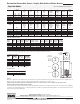
Single Wall Models
Meet or exceed ASHRAE 90.1b (current standard)
Model
Number
Approx.
Shipping
Weight
lbs.
A
Floor to
Heater
Top
in.
C
Floor to
T&P
Conn.
in.
B
Jacket
Dia.
in.
Capacity
SW-2-30-L
SW-2-40R-L
SW-2-50R-L
SW-2-65-L
SW-2-80-L
SW-2-120-L
U.S.
Gal.
29
37
43
57
71
110
Imp.
Gal.
24
31
36
47
59
92
33
5
/
8
41
1
/8
46
1
/4
59
1
/4
59
62
1
/2
28
1
/
4
34
3
/8
40
1
/8
53
1
/8
52
7
/8
55
3
/4
164
185
195
225
250
370
22
22
22
22
24
28
1
/4
E
Floor to
Exchanger
Outlet
in.
5
3
/
8
5
3
/8
5
3
/8
5
3
/8
5
3
/8
6
3
/8
27
1
/
2
27
1
/2
27
1
/2
27
1
/2
27
1
/2
28
1
/2
34
3
/
8
41
7
/8
47
60
59
3
/4
63
1
/4
D
Floor to
Water
Conn.
in.
Model
Number
Approx.
Shipping
Weight
kg.
A
Floor to
Heater
Top
mm.
C
Floor to
T&P
Conn.
mm.
B
Jacket
Dia.
mm.
Capacity
SW-2-30-L
SW-2-40R-L
SW-2-50R-L
SW-2-65-L
SW-2-80-L
SW-2-120-L
Liters
110
140
163
216
269
416
854
1045
1175
1505
1499
1588
718
873
1019
1349
1343
1416
74
85
89
102
114
167
559
559
559
559
610
718
E
Floor to
Exchanger
Outlet
mm.
137
137
137
137
137
162
F
Floor to
Exchanger
Inlet
in.
F
Floor to
Exchanger
Inlet
mm.
699
699
699
699
699
720
11
1
/
2
11
1
/2
11
1
/2
11
1
/2
11
1
/2
11
1
/2
G
Floor to
Aquastat
in.
G
Floor to
Aquastat
mm.
292
292
292
292
292
292
873
1064
1194
1524
1518
1607
D
Floor to
Water
Conn.
mm.
Residential PowerStor Series
®
Single-Wall Indirect Water Heater
General:
All units are certified at 300 PSI (2068 kPa) test pressure and 150 PSI (1034 kPa) working pressure. Potable water connections are 3/4" (19mm) NPT on 8"
(203mm) centers. The 120 gallon model has 1" (25mm) NPT potable water connections on 8" (203 mm) centers.
Dimensions and specifications subject to change without notice in accordance with our policy of continuous product improvement.
Suitable for Water (Potable) Heating and Space Heating.
Toxic chemicals, such as those used for boiler treatment, shall NEVER be introduced into the potable side of this system. The potable side may NEVER be
connected to any existing heating system or component(s) previously used with a non-potable water heating appliance. The heat exchanger side of the unit
may be used in space heating applications.
Based on 200°F boiler water temperature and 50°F
potable water inlet.
Model
Number
140°F 115°F
DOE Water Heater Performance
SW-2-30-L
SW-2-40R-L
SW-2-50R-L
SW-2-65-L
SW-2-80-L
SW-2-120-L
140°F 115°F
Maximum First
Hour Rating
(Gal.) @
226
235
244
258
272
309
342
351
360
374
388
425
140°F 115°F
3.3
3.3
3.3
3.3
3.3
3.3
5.2
5.2
5.2
5.2
5.2
5.2
Continuous
Draw Rating
(Gal./Min.) @
Approximate Boiler
Output Needed
For Ratings
(BTU/Hr.)
Approximate
Boiler Output
Needed for
Ratings (BTU/Hr.)
180,000
180,000
180,000
180,000
180,000
180,000
55,000
55,000
55,000
55,000
D
A
F
E
G
C
B
POTABLE
CONNECTIONS
ANODE ROD
CONFIGURATIONS
SW-2-30-L
SW-2-40R-L
SW-2-50R-L
SW-2-65-L
SW-2-80-L
SW-2-120-L
(TYPICAL)
Model
Number
AHRI Certified Water Heater Ratings
SW-2-30-L
SW-2-40R-L
SW-2-50R-L
SW-2-65-L
SW-2-80-L
SW-2-120-L
First Hour
Delivery
@ 135°F
(Gal.)
197
205
210
215
235
265
Continuous
Draw Rating
@ 135°F
(Gal./Hr.)
180
180
180
175
175
175
Standby
Heat Loss
Rating
(°F/Hr.)
1.2
1.1
0.9
0.7
0.6
0.4
Minimum
Heat Source
Flow Rate
(Gal./Min.)
13.7
13.7
13.7
13.7
13.7
13.7
Minimum
Output Rate
of Heat Source
(BTU/Hr.)
120,000
120,000
120,000
115,000
115,000
115,000
Model
Number
SW-2-30-L
SW-2-40R-L
SW-2-50R-L
SW-2-65-L
SW-2-80-L
SW-2-120-L
First Hour
Delivery
@ 57°C
(Liters)
746
776
795
814
889
1003
Continuous
Draw Rating
@ 57°C
(Liters/Hr.)
681
681
681
662
662
662
Standby
Heat Loss
Rating
(°C/Hr.)
0.67
0.61
0.50
0.39
0.33
0.22
Minimum
Heat Source
Flow Rate
(Liters/Min.)
51.8
51.8
51.8
51.8
51.8
51.8
Minimum
Output Rate
of Heat Source
(kW/Hr.)
35.0
35.0
35.0
34.0
34.0
34.0
These certified ratings were obtained with a heat source output rate and flow rate as specified and a
180°F (82°C) boiler water supply temperature. Other results will be obtained under different conditions.
Heat Exchanger Head Loss
GPM
2
0.01
5
0.20
8
0.50
10
0.80
12
1.20
Ft. of Hd. Loss
Printed in U.S.A.554-G-0322