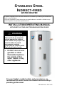
STAINLESS STEEL INDIRECT-FIRED WATER HEATER A Spanish language version of these instructions is available by contacting the manufacturer listed on the rating plate. La version Espanola de estas instruccions se puede obtener al escribirle a la fábrica cuyo nombre aparece in la placa de especificaciones.
CONGRATULATIONS! You have purchased one of the finest water heaters on the market today! This installation, operation, and instruction manual will explain in detail the installation and maintenance of your new Indirect Water Heater. We strongly recommend that you contact a plumbing professional for the installation of this water heater. We require that you carefully read this manual, as well as the enclosed warranty, and refer to it if questions arise.
SECTION I IMPORTANT INFORMATION -READ CAREFULLYThe equipment must be installed in accordance with the installation regulations required in the area of the installation. These regulations must be carefully followed in all cases. Authorities having jurisdiction must be consulted before installations are made.
Important Information continued- CAUTION The maximum boiler water supply temperature to the indirect heat exchanger must not exceed 240°F (115°C). Improper water quality will reduce the expected life of the water heater. Hard water, sediment, high or low PH and high levels of chlorides in the domestic water should be avoided. Be sure that PH value falls between 6 and 8 and dissolved chlorides are less than 100 ppm.
Important Information continued- DANGER This water heater is supplied with an adjustable thermostat to control water temperature. Hot water temperatures required for automatic dishwasher and laundry use can cause scald burns resulting in serious personal injury and/or death. The temperature at which injury occurs varies with the person’s age and the time of exposure. The slower response time of disabled persons increases the hazards to them.
Important Information continued- WARNING Improper installation, adjustments, alteration, service or maintenance can cause property damage, personal injury or loss of life. Failure to follow all instructions in the proper order can cause personal injury or death. Read and understand all instructions, including all those contained in component manufacturer’s manuals, which are provided with the appliance before installing, starting-up, operating, maintaining, or servicing this appliance.
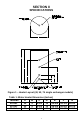
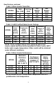
SECTION II SPECIFICATIONS Figure 1 – Heater Layout (40, 52, 75 single exchanger models) Table 1: Water Heater Dimension (Inches) MODEL A B C D E F G 40-Gal. 52-Gal. 75-Gal.
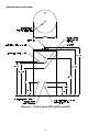
Specifications continued- Figure 2 – Tank Layout (120 gallon model) 8
Specifications continued- Table 2: Water Heater Capacities MODEL Tank Coil Cap. Cap. (Gal) (Gal) 40-Gal. 52-Gal. 75-Gal. 120-Gal. 40 52 75 119 1.2 1.6 1.6 4.6 Dry Weight (Lbs) 90 100 125 270 Wet Weight (Lbs) 415 525 745 1257 Table 3: AHRI Certified Water Heater Ratings MODEL First Hour Rating (Gal/Hr) Continuous Draw Rating (Gal/Hr) Standby Heat Loss Rating (°F/Hr) Minimum Output of Heat Source (BTU/Hr) Minimum Heat Source Flow Rate (Gal/Min) 40-Gal. 52-Gal. 75-Gal. 120-Gal.
Specifications continued- Table 5: Water Heater Performance MODEL 40-Gal. 52-Gal. 75-Gal. 120-Gal Hot Water Availability (Minutes) 7.3 9.7 14.3 23.8 Coil Heat Transfer Area (Sq Ft) 7.6 10.0 10.0 21.3 Pressure Drop (Feet of Head) 6.0 @ 8 gpm 6.2 @ 8 gpm 6.2 @ 8 gpm 8.5 @ 11 gpm NOTICE If the boiler takes longer to heat up from a cold start than the water availability as noted above, hot water shortage may occur.
SECTION III GENERAL INFORMATION FEATURES This water heater contains the following features: HEAT EXCHANGER -- The heat exchanger (coil) has 3/4” NPT female fittings. These water heaters with stainless steel single-wall heat exchangers meet the Uniform Plumbing Code for installation in all potable water systems provided that: • • • • The boiler water (including additives) is practically nontoxic, having toxicity rating of class of 1 as listed in Clinical Toxicology of Commercial Products.
General Information continued- TEMPERATURE AND PRESSURE RELIEF VALVE WARNING Keep clear of the combination temperature and pressure relief valve discharge line outlet. The discharge may be hot enough to cause scald injury. The water is under pressure and may splash.
General Information continued- WARNING Install a discharge line so that water discharged from the temperature and pressure relief valve will exit within six (6) inches above, or any distance below, the structural floor and cannot contact any live electrical part. The discharge line is to be installed to allow for complete drainage of both the temperature and pressure relief valve and the discharge line. The discharge opening must not be subjected to blockage or freezing.
SECTION IV PRE-INSTALLATION UNPACKING INSPECT SHIPMENT carefully for any signs of damage. If damage is noted, do not install the product. Contact the shipper or manufacturer. All equipment is carefully manufactured, inspected, and packed. Our responsibility ceases upon delivery of the packaged water heater to the carrier in good condition. NOTE: Any claims for damage or shortage in shipment must be filed immediately against the carrier by the consignee.
Pre-installation continued- NOTICE Increasing the boiler DOE heating capacity above the values listed in Table 3 will not increase the rating of the water heater. 2. Circulator Sizing – Refer to Table 5 for the corresponding pressure drop through the coil for the given model. Calculate the pressure drop of all straight pipe and fittings on the supply and return of the water heater at the selected flow rate. Add the piping/fitting pressure drop to the pressure drop through the water heater coil.
Pre-installation continued- a) Boiler DOE heating capacity is 100,000 BTU per hour or less, or b) When boiler output required to satisfy domestic hot water demand is at least 50% of the boiler output required to satisfy space heating demand, or c) When an interruption in space heating can be tolerated during a long domestic hot water draw. 2. Non-Priority – Boiler output is divided between space heating and domestic hot water heating.
Pre-installation continued- CAUTION Do NOT drop water heater. Do NOT bump water heater jacket against floor. APPLIANCE LOCATION 1. Boiler Location – Locate the indirect-fired water heater as close to the boiler as practical. 2. Fixture Locations – For fastest delivery of hot water, place the indirect-fired water heater close to points of use. ADDITIONAL RECOMMENDED COMPONENTS 1. Shut-off Valves – Allows isolation of water heater from domestic water system and/or boiler system during service. 2.
SECTION V WATER CONNECTIONS WARNING FAILURE TO INSTALL AND MAINTAIN A NEW, LISTED TEMPERATURE AND PRESSURE RELIEF VALVE WILL RELEASE THE MANUFACTURER FROM ANY CLAIM WHICH MIGHT RESULT FROM EXCESSIVE TEMPERATURE AND PRESSURES. Keep clear of the temperature and pressure relief valve discharge line outlet. The discharge may be hot enough to cause scald injury. The water is under pressure and may splash.
Water Connections continued- 2. If this water heater is installed in a closed water supply system, such as one having a back-flow preventer in the cold water supply, provisions must be made to control thermal expansion. DO NOT operate this water heater in a closed system without provisions for controlling thermal expansion. Warranties do not cover damages from thermal expansions such as pressure bulges and/or deformities. A properly sized expansion tank will alleviate most problems.
Water Connections continued- CONNECT WATER BOILER SUPPLY PIPING 1. For a space heating system that utilizes ZONE VALVES, refer to Figure 3. The indirect-fired water heater connection labeled “FROM BOILER SUPPLY” should be piped to the boiler supply piping. Mount the circulator making sure the flow arrow points toward the water heater. The use of shut-off valves and unions are recommended for future service convenience. The use of an air separator and vent is recommended to eliminate air in the system.
Water Connections continued- Figure 4 - Water Boiler Piping with Circulators CONNECT STEAM BOILER SUPPLY PIPING Figure 5 represents a typical steam boiler connection diagram. Refer to the boiler installation manual or contact the boiler manufacturer for an appropriate piping diagram. The use of a union, shut-off valves, and a drain valve is recommended for future service convenience. The use of an in-line “Y”-style strainer is required to prevent accumulation of sludge in the water heater’s coil.
Water Connections continued- NOTICE Typical steam boiler without connections available below the water line is not recommended due to insufficient water temperature, especially during warmer months when the space heating system is not operational. Boiler water temperature at the bottom of a steam boiler can be 50°F lower than the boiler’s water temperature limit setting during such periods. FILL BOILER SYSTEM 1.
SECTION VI ELECTRICAL CONNECTIONS Install electric wiring in accordance with National Electric Code or the Canadian Electrical Code and local regulations. See the boiler’s installation manual for wiring diagrams. DANGER Positively assure all electrical connections are unpowered before attempting installation or service of electrical components or connections of the water heater or building. Lock out all electrical boxes with padlock once power is turned off.
Electrical Connections continued- AT NO TIME SHOULD WATER HEATER OPERATION TAKE PLACE WITHOUT THE COVER ON THE CONTROL.
SECTION VII OPERATING INSTRUCTIONS WARNING Water heaters are heat-producing appliances. To avoid damage or injury there must be no materials stored against the water heater, and proper care must be taken to avoid unnecessary contact (especially by children) with the water heater. UNDER NO CIRCUMSTANCES SHALL FLAMMABLE MATERIALS, SUCH AS GASOLINE OR PAINT THINNER BE USED OR STORED IN THE VICINITY OF THE WATER HEATER OR IN ANY LOCATION FROM WHICH FUMES COULD REACH THE WATER HEATER.
Operating Instructions continued- WATER TEMPERATURE ADJUSTMENT WARNING SCALDING This water heater can deliver scalding temperature water at any faucet in the system. Be careful whenever using hot water to avoid scalding injury. By setting the thermostat on this water heater to obtain an increased water temperature, you may create the potential for scald injury.
Operating Instructions continued- CAUTION Before adjusting the aquastat, turn OFF all power supplied to the indirect-fired water heater. For the most energy efficient operation, adjust the aquastat for the minimum water temperature necessary to meet domestic hot water needs. Refer to Figure 8. Use a small flat screwdriver to rotate the temperature dial through the hole directly below the temperature indication window. The temperature setting is aligned with the notch in this window.
Operating Instructions continued- Adjusting to a lower temperature setting will not immediately affect water temperature. Draw sufficient water or allow the water heater to remain idle until a heat-up cycle is initiated. After the heater’s heat-up cycle is complete, check the water temperature at a faucet to determine if further adjustment is necessary. Adjusting to a higher temperature may not immediately affect water temperature.
SECTION VIII MAINTENANCE This indirect-fired water heater is intended to provide a service life of many years. Components that require service, however, may be subject to failure. Failure to use the correct procedures or parts in these circumstances may make the water heater unsafe. The owner should arrange to have the following inspections and simple maintenance procedure performed by qualified service personnel at the frequencies suggested. 1.
Maintenance continued- CAUTION Before manually operating the valve, make sure that a drain line has been attached to the valve to direct the discharge to an open drain. Failure to take this precaution could mean contact with extremely hot water discharging from the valve during this checking operation. 3. Sediment (Annual, but harsh water quality may dictate more frequent service) – Depending on water conditions, a varying amount of sediment may collect in the tank.
SECTION IX TROUBLESHOOTING GUIDE PROBLEM CAUSE SOLUTION Refer to boiler installation instructions Boiler does not operate Check main service switch Check fused disconnect Circulator does not operate Improper aquastat setting or calibration Zone valve does not open (if used) No hot water at faucet Check power supply Replace as necessary Turn tank aquastat to appropriate setting Check power supply Replace as necessary Check fuse and replace Electrical problem (relay, wiring, etc.
Troubleshooting Guide continued- PROBLEM Water at faucet too hot Insufficient hot water Boiler cycles more than 5 times per day in summer CAUSE Improper system plumbing Improper system wiring SOLUTION Compare plumbing to Section V Compare wiring to Section VI Aquastat set too high Lower aquastat setting. See Section VII Aquastat setting too low Adjust aquastat to higher setting.
SECTION X PARTS LIST PART NAME & DESCRIPTION 1. Temperature and Pressure Relief Valve 3. Aquastat 2. Aquastat Well 4.
Contact your supplier or plumbing professional for replacement parts or contact the company at the address given on the rating plate of the water heater. Provide the part name, model, and serial numbers of the water heater when ordering parts. READ THE WARRANTY FOR A FULL EXPLANATION OF THE LENGTH OF TIME THAT PARTS AND THE WATER HEATER ARE WARRANTED. Manufactured under one or more of the following U.S.
NOTES 35
NOTES 36