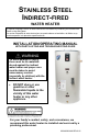
STAINLESS STEEL INDIRECT-FIRED WATER HEATER A Spanish language version of these instructions is available by contacting the manufacturer listed on the rating plate. La version Espanola de estas instruccions se puede obtener al escribirle a la fábrica cuyo nombre aparece in la placa de especificaciones.
CONGRATULATIONS! You have purchased one of the finest water heaters on the market today! This installation, operation, and instruction manual will explain in detail the installation and maintenance of your new Indirect-Fired Water Heater. We strongly recommend that you contact a plumbing professional for the installation of this water heater. We require that you carefully read this manual, as well as the enclosed warranty, and refer to it if questions arise.
SECTION I IMPORTANT INFORMATION -READ CAREFULLY- CAUTION The maximum boiler water supply temperature to the indirect heat exchanger must NOT exceed 240°F (115°C). Improper water quality will reduce the expected life of the water heater. Hard water, sediment, high or low PH and high levels of chlorides in the domestic water should be avoided. Be sure that PH value falls between 6 and 8 and dissolved chlorides are less than 100 ppm.
Important Information continued- The equipment must be installed in accordance with the installation regulations required in the area of the installation. These regulations must be carefully followed in all cases. Authorities having jurisdiction must be consulted before installations are made.
Important Information continued- DANGER DO NOT store or use gasoline or other flammable, combustible, or corrosive vapors and/or liquids in the vicinity of this or any other appliance. IF YOU SMELL GAS: • DO NOT try to light any appliance. • DO NOT touch any electric switch; DO NOT use any telephone in your building. • Immediately call your gas supplier from a telephone in another building. Follow the gas supplier’s instructions. • If you cannot reach your gas supplier, call the fire department.
Important Information continued- WARNING Installation is NOT complete unless a properly sized/capacity temperature and pressure relief valve is installed into the top of the water heater. See the General Information section of this manual for details. This water heater contains very hot water under high pressure. DO NOT unscrew any pipe fittings or attempt to disconnect any components of this water heater without positively assuring the water is cool and has no pressure.
Important Information continued- WARNING It is the responsibility of the installing contractor to see that all controls are correctly installed and are operating properly when the installation is complete. DO NOT operate the water heater with jumpered or absent controls or safety devices. DO NOT tamper with or alter the water heater and/or controls. DO NOT operate the water heater if any external part has been under water.
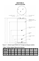
SECTION II SPECIFICATIONS Figure 1 – Heater Layout (30,40, 50, 75 single exchanger models) Table 1: Water Heater Dimension (Inches) MODEL A B C D E 24 2-1/4 10 16-1/2 22-5/8 30-Gal 24 2-1/4 10 18-3/4 24-3/4 40-Gal 24 2-1/4 10 19-1/2 29-1/4 50-Gal 24 2-1/4 10 19-1/2 33-5/8 75-Gal 8 F G H 22-1/2 29-1/8 39-3/4 56-1/2 31-5/8 38-1/4 48 65-5/8 32-1/2 38-7/8 48-7/8 66-1/4
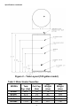
Specifications continued- Figure 2 – Tank Layout (120 gallon model) Table 2: Water Heater Capacities MODEL 30-Gal. 40-Gal. 50-Gal. 75-Gal. 120-Gal. Tank Coil Cap. Cap. (Gal) (Gal) 29.2 1.0 37.5 1.4 50.0 1.4 72.5 2.5 111.0 3.
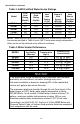
Specifications continued- Table 3: AHRI Certified Water Heater Ratings Model First Hour Rating (Gal/Hr) Continuous Draw Rating (Gal/Hr) Standby Heat Loss Rating (°F/Hr) Minimum Output of Heat Source (BTU/Hr) Minimum Heat Source Flow Rate (Gal/Min) 30-Gal. 40-Gal. 50-Gal. 75-Gal. 120-Gal. 178 237 269 367 409 160 209 229 307 319 0.8 0.6 0.5 0.4 0.3 120,000 135,000 145,000 193,000 199,000 14.0 14.0 14.0 14.0 9.
SECTION III GENERAL INFORMATION FEATURES This water heater contains the following features: HEAT EXCHANGER – The heat exchanger (coil) has 1” NPT female fittings. These water heaters with stainless steel single-wall heat exchangers meet the Uniform Plumbing Code for installation in all potable water systems provided that: • • • • The boiler water (including additives) is practically non-toxic, having toxicity rating of class of 1 as listed in Clinical Toxicology of Commercial Products.
General Information continued- TEMPERATURE AND PRESSURE RELIEF VALVE WARNING Keep clear of the combination temperature and pressure relief valve discharge line outlet. The discharge may be hot enough to cause scald injury. The water is under pressure and may splash.
General Information continued- WARNING Install a discharge line so that water discharged from the temperature and pressure relief valve will exit within six (6) inches above, or any distance below, the structural floor and cannot contact any live electrical part. The discharge line is to be installed to allow for complete drainage of both the temperature and pressure relief valve and the discharge line. The discharge opening must not be subjected to blockage or freezing.
Pre-installation continued- IMPORTANT DECISIONS REQUIRED BEFORE INSTALLATION SIZING 1. Boiler DOE Heating Capacity – The indirect-fired water heater will provide the rated performance only if used in conjunction with a heat source with a DOE heating capacity (Heat Output) at least as much as the minimum noted in Table 3. If the heat source has less capacity, the output of the tank will be reduced.
Pre-installation continued- 2. Zone Valves – Select a valve with a low-pressure drop to assure adequate flow through the water heater. 3. Hybrid – The space heating zone can be zoned using zone valves and the indirect-fired heater zoned with a circulator. DOMESTIC HOT WATER PRIORITY Two options are available, Priority and Non-Priority. 1. Priority – Demand for space heating is interrupted or postponed until the domestic hot water demand is satisfied.
Pre-installation continued- Recommended Service Clearances Non-Piping Side 6”(15.2cm) Front (Aquastat) Rear Top 30”(76.2cm) 1”(2.5cm) 12”(30.5cm) Table 6: Service Clearances CAUTION DO NOT drop water heater. DO NOT bump water heater jacket against floor. Appliance Location 1. Boiler Location – Locate the indirect-fired water heater as close to the boiler as practical. 2. Fixture Locations – For fastest delivery of hot water, place the indirect-fired water heater close to points of use.
SECTION V WATER CONNECTIONS WARNING FAILURE TO INSTALL AND MAINTAIN A NEW, LISTED TEMPERATURE AND PRESSURE RELIEF VALVE WILL RELEASE THE MANUFACTURER FROM ANY CLAIM WHICH MIGHT RESULT FROM EXCESSIVE TEMPERATURE AND PRESSURES. Keep clear of the temperature and pressure relief valve discharge line outlet. The discharge may be hot enough to cause scald injury. The water is under pressure and may splash. INSTALL TEMPERATURE AND PRESSURE RELIEF VALVE (if not factory installed).
Water Connections continued- 3. After installation of the water lines, open the main water supply valve and fill the water heater. While the water heater is filling, open several hot water faucets to allow air to escape from the water system. When steady streams of water flow through the faucets, close them and check all water connections for possible leaks. 4. NEVER OPERATE THE WATER HEATER WITHOUT FIRST BEING CERTAIN THAT IT IS FILLED WITH WATER.
Water Connections continued- Figure 3 - Water Boiler Piping with Zone Valves 2. For a space heating system that utilizes CIRCULATORS, refer to Figure 4. The indirect-fired water heater connection labeled “FROM BOILER SUPPLY” should be piped to the boiler supply piping. Mount the circulator making sure the flow arrow points toward the water heater. The use of shut-off valves and unions are recommended for future service convenience.
Water Connections continued- CONNECT STEAM BOILER SUPPLY PIPING Figure 5 represents a typical steam boiler connection diagram. Refer to the boiler installation manual or contact the boiler manufacturer for an appropriate piping diagram. The use of a union, shut-off valves, and a drain valve is recommended for future service convenience. The use of an in-line “Y”-style strainer is required to prevent accumulation of sludge in the water heater’s coil.
SECTION VI ELECTRICAL CONNECTIONS Install electric wiring in accordance with National Electric Code or the Canadian Electrical Code and local regulations. See the boiler’s installation manual for wiring diagrams. DANGER Positively assure all electrical connections are unpowered before attempting installation or service of electrical components or connections of the water heater or building. Lock out all electrical boxes with padlock once power is turned OFF.
Electrical Connections continued- AT NO TIME SHOULD WATER HEATER OPERATION TAKE PLACE WITHOUT THE COVER ON THE CONTROL. Figure 6 - Aquastat Control SECTION VII OPERATING INSTRUCTIONS WARNING Water heaters are heat-producing appliances. To avoid damage or injury there must be NO materials stored against the water heater, and proper care must be taken to avoid unnecessary contact (especially by children) with the water heater.
Operating Instructions continued- SYSTEM START-UP Follow boiler installation instructions to place boiler in operation. SEQUENCE OF OPERATIONS 1. Aquastat senses stored water temperature below desired setpoint. a. Domestic hot water priority only: Normally closed contacts open to interrupt space heating. b. Normally open contact closes, energizing the domestic hot water circulator. 2. Aquastat senses stored water temperature at desired setpoint. a.
Table 7 details the approximate relationship of water temperature and time with regard to scald injury and may be used as a guide in determining the safest water temperature for your applications.
Operating Instructions continued- Figure 8 - Aquastat Control After the indirect-fired water heater completes a heat-up cycle, check the water temperature at a faucet. Allow enough water to flow to ensure that the water temperature reflects the tank temperature. Adjust the water heater’s temperature setting as necessary. Adjusting to a lower temperature setting will not immediately affect water temperature. Draw sufficient water or allow the water heater to remain idle until a heat-up cycle is initiated.
SECTION VIII MAINTENANCE This indirect-fired water heater is intended to provide a service life of many years. Components that require service, however, may be subject to failure. Failure to use the correct procedures or parts in these circumstances may make the water heater unsafe. The owner should arrange to have the following inspections and simple maintenance procedure performed by qualified service personnel at the frequencies suggested. 1.
Maintenance continued- If the temperature and pressure relief valve on the heater discharges periodically or continuously, it may be due to thermal expansion of water in a closed water supply system, or it may be due to a faulty relief valve. Thermal expansion is the normal response of water when it is heated. In a closed system, thermal expansion will cause the system pressure to build until the relief valve actuation pressure is equaled.
SECTION IX TROUBLESHOOTING GUIDE PROBLEM CAUSE Boiler does not operate No hot water at faucet SOLUTION Refer to boiler installation instructions. Check main service switch. Check fused disconnect. Check power supply. Circulator does not operate Replace as necessary. Improper aquastat setting or calibration Turn tank aquastat to appropriate setting. Zone valve does not open (if used) Check power supply. Replace as necessary. Check fuse and replace. Electrical problem (relay, wiring, etc.
Troubleshooting Guide continued- PROBLEM Insufficient hot water Boiler cycles more than 5 times per day in summer CAUSE Aquastat setting too low SOLUTION Adjust aquastat to higher setting. See Section VII. Undersized boiler with no priority to domestic hot water Rewire for priority. Peak use of hot water is greater than tank storage capacity Determine peak usage and compare to tank capacity. Faulty tank aquastat Replace aquastat. Excessive demand Reduce demand or consider larger tank.
SECTION X PARTS DIAGRAM PART NAME & DESCRIPTION 1. Temperature and Pressure Relief Valve 2. Aquastat 3. Drain Valve 4. Diptube 5. T&P/Drain Escutcheon 6.
Contact your supplier or plumbing professional for replacement parts or contact the company at the address given on the rating plate of the water heater. Provide the part name, model, and serial numbers of the water heater when ordering parts. This product is covered under or more of the following patents and or READ THE WARRANTY FOR one A FULL EXPLANATION OF THE LENGTH OF patent pending applications: CA2,430,807 CA2,844,271 GB1369647 TIME THAT PARTS AND THE WATER HEATER AREEP1369647 WARRANTED.
NOTES 32