
Installation / Operation Instruction Manual

8
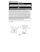
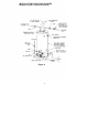
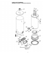
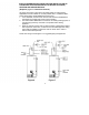
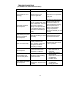
PARTS LIST
(Replaces pg. 30 in instruction manual.)
PART NAME AND DESCRIPTION
1. Draft Diverter 14a. Resistance Temperature Detector
2. Jacket Head Pan 15. Drain Valve
3. Jacket 16. Gas Valve
4. Outer Door 17. Wire Harness
5. Magnesium Anode–Hot Water Outlet 18. Radiant Burner
6. Flue Baffle Assembly 19. Orifice
7. Dip Tube–Cold Water Inlet 20. Manifold Mount
8. Temperature and Pressure Relief Valve 20a. High Temperature Limit Switch
9. Glass Lined Tank 21. Gas Feedline to Burner
10. Secondary-Air Restrictor Plate 22. Gas Feedline to Pilot
11. Combustion Chamber Assembly 23. Spark Igniter
12. Jacket Base Pan 24. Thermopile
13. Inner Door Gasket 25. Pilot Assembly
14. Inner Door Assembly