
Installation / Operation Instruction Manual


71
Sensor resistance charts
RTG-L-199/160N/X1 – 6 721 827 274 (2022/06)
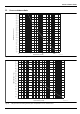
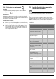
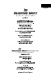
11 Sensor resistance charts
Fig. 63 Inlet, outlet and heat exchanger water temperature sensors characteristics
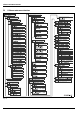
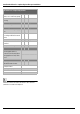
Fig. 64 Flue gases and condensing unit flue gases temperature sensors characteristics
-40
-22
-4 14
32 50 68 86 104 122 140 158 176 194
(-40)
(-30)
(-20)(-10)(0)(10)(20)(30)(40)(50)(60)(70)(80)(90)(100)(110)(120)
212 2
30 248
0.1
1
100
RESISTANCE (KOHM)
TEMPERA
TURE ºF (ºC)
6720816948-40.1V
10
-40
-4
32 68 104 140 176 212 284 320 392 428 464
(-40)
(-20)
(0)(20)(40)(60)(80)(100)(140)(160)(200)(220)(240)
248
(120)
356
(180)
0.01
0.1
1
10
100
RESISTANCE (KOHM)
TEMPERATURE ºF (ºC)
6720816948-41.1V