
Installation / Operation Instruction Manual

55
Maintenance and service
RTG-L-199/160N/X1 – 6 721 827 274 (2022/06)
▶ Open a hot water tap and check for gas leak (e.g. use leak
detector fluid, like water and soap, over and around the
metal plate) and act accordingly.
▶ Place the front cover.
▶ Access service mode by pressing and holding down at the
same time, , and for 3 seconds.
▶ Press buttons or until the display shows “P7”.
▶ Press .
▶ Press buttons or to choose LP (LPG).
▶ Press the button for 3 secs. to save your selection.
The selected temperature blinks.
▶ Update “TYPE OF GAS” in the rating plate of the appliance
using the label provided with the gas conversion kit.
▶Confirm combustion adjustment and, if necessary, adjust
the parameters P1 and P2, see chapter 8.11 for more
information.
7 Maintenance and service
WARNING:
Maintenance must be done trained or qualified contractor.
DANGER:
▶ Always shut off the electrical power supply, shut off the
manual gas valve and shut off the water valves whenever
servicing.
WARNING:
▶ Replace all dismantled joints and o-rings with new ones.
▶ Consult spare part list at www.bradfordwhite.com.
NOTICE:
▶ Inspect and clean the complete water heating system once
a year.
▶ Follow points 5 and 6 in Table 28 after 400 operation hours
or 25000 cycles (whichever occurs first), see
chapter 6.5.1 (Op. Data).
▶ Inspect the water heater and components for wear or
fatigue. Immediately repair all faults to avoid damage to the
system.
Table 28
7.1 Required annual maintenance
(To remove front cover, see page 12).
Venting System
NOTICE:
Venting system blocked!
▶ For horizontally vented appliances, keep the area around
the venting system free of snow or ice to prevent blockage.
• Venting system - inspect inside of flue pipe for any blockage
or restriction.
• Observe burner flames during heater operation (front
cover must be removed). Burner flames should be steady
and blue. Yellow, inconsistent (bouncing) flames may be an
indication of poor ventilation or combustion air supply.
Inspect the combustion air inlet pipe for blockage or debris.
Inspect combustion air and exhaust terminations for
blockage or debris.
Heat Exchanger
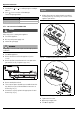
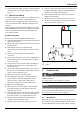
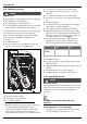
• Inspect burner observation window (Fig. 66) for cracks or
spillage of flue gases. Observe burner flames during heater
operation. Flames should be steady and blue with no signs
of yellowing. Yellow burner flames are an indication of
improper combustion. Refer to Section 4.6, page 18 of this
manual to verify exhaust system and combustion air supply
meets manufacturer's specifications.
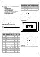
Annual maintenance table
Every year
1. Inspect venting system X
2. Inspect combustion chamber X
3. Inspect burner X
1)
1) Proceed with air filter cleaning or replacement if error code
CE, CF and C2 is displayed. Check the flue exhaust for
blockage (appliance is protected against flue blockage).
4. Inspect pressure relief X
5. Inspect water filter X
6. Heat Exchanger Descaling X
2)
2) Proceed with heat exchanger descaling whenever error
codes AA and E5 are displayed (appliance is protected
against over heating in case of scaling, see table 17, Water
Quality).
7. Inspect condensate siphon X
8. Inspect air filter X
1)