
Installation / Operation Instruction Manual

39
Installation instructions
RTG-L-199/160N/X1 – 6 721 827 274 (2022/06)
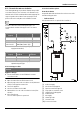
4.11 Domestic hot water recirculation
The following drawings are provided to illustrate two possible
recirculation designs. These schematic is for illustration only
and must not be used for actual Installation without appropriate
engineering and technical advice from a properly licensed
professional in the locality where the installation is made.
In order to reduce the heat loss through the pipes, it’s
recommended to insulate all the pipes in the recirculation
circuit.
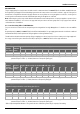
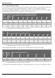
Table 18 Maximum total combined pipe length (hot water
supply and return lines)
Table 19 Pressure Loss in copper fittings expressed as
equivalent length of pipe
4.11.1 Start up procedure
NOTICE:
Appliance damage!
▶ Ensure that the water circuit is filled before activate
recirculation mode.
▶ Open a hot water faucet to fill the water circuit.
▶ Open the purge valve in the recirculation circuit (dedicated
mode) near the appliance water inlet.
▶ Turn on the appliance.
▶ Set the recirculation mode in HMI.
▶ Wait until there is no air in the recirculation circuit (a few
minutes).
▶ Close water faucets.
The recirculation system is operational.
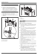
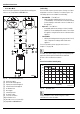
4.11.2 Recirculation options
House Recirculation
Compatible with dedicated return line and cross over mode
with thermal by-pass valve.
• Dedicated mode
A dedicated return line is required in the installation.
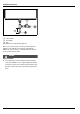
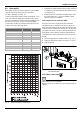
Fig. 30 Recirculation application
[1] Cold inlet supply
[2] Check valve field supplied
[3] Expansion tank field supplied
[4] Purge Valve recirculation circuit
[5] Shutoff valves field supplied
[6] Cold water inlet
[7] Gas supply
[8] Shutoff gas valve
[9] Hot water outlet
[10] Pressure relief valve
Pipe Diameter
(copper)
Maximum Length 90° Elbows
¾" 250 ft (76m) 15
½" 166 ft (50m) 15
Combination of
both ¾" and ½"
100 ft (30m) with ¾" pipe +
100 ft (30m) with ½" pipe
15
Pipe Diameter
(copper)
Equivalent Length
90° Elbow 45° Elbows
½" 1 ft 0.5 ft
¾" 2 ft 0.5 ft