
Installation / Operation Instruction Manual

35
Installation instructions
RTG-L-199/160N/X1 – 6 721 827 274 (2022/06)
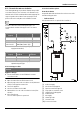
GAS LINE SIZING
The gas supply piping for a single heater should be sized for a maximum draw of 199000 BTU/hr for the RTG-L-199N/X1. Measure
the length of the gas supply line from the building's gas main to the heater and use section 4.8.1 and 4.8.2, page 35 or the gas line
manufacturer’s sizing tables to determine the pipe diameter necessary. If there are more gas appliances on the line, size the gas line
according to the total maximum amount of BTU draw input rating for all appliances combined.
Note: Undersizing the gas line may result in diminished hot water flow rate and temperature, or improper appliance operation (noise
and combustion instabilities). See section 4.14, page 44 for the procedure to measure gas pressure. Proper gas pressure must be
confirmed at time of installation.
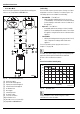
4.8.1 Gas Line Sizing Tables for NATURAL GAS
For your convenience see below for an excerpt from gas line sizing tables for a single NG appliance. For details see the current NFPA
54.
Required input for 160000 / 199000 BTU/hr for the RTG-L-160/199N/X1. The gas supply system must be sized for the combined
total maximum BTU/hr load requirements of all gas appliances running simultaneously.
The tables below show the maximum capacity of the gas supply pipe in cubic feet per hour. Please contact your local gas supplier for
the energy content of the gas to determine the BTU/hr capacity. Use 1,000 BTU/cubic foot for rough estimations.
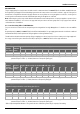
Table 11 Maximum pipe capacity in cubic feet of Natural Gas per hour for gas pressures of <2.0 psig (55" WC or 138 mbar) and a
pressure drop of 0.5" W.C. (1.25 mbar) based on 0.60 specific gravity gas).
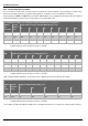
Table 12 Maximum pipe capacity in cubic feet of Natural Gas per hour for gas pressures of <2.0 psig (55" WC or 138 mbar) and a
pressure drop of 3.0” W.C. (7.5 mbar) based on 0.60 specific gravity gas.
Table 13 Maximum pipe capacity in cubic feet of Natural Gas per hour for gas pressures of <2.0 psig (55" WC or 138 mbar) and a
pressure drop of 0.5" W.C. (1.35 mbar) based on 0.60 specific gravity gas).
* EHD = Equivalent Hydraulic Diameter. The greater the value of EHD, the greater the gas capacity of the tubing.
Initial Supply Pressure of 8.0" w.c. or Greater
Nominal
Iron Pipe
Size, inches
Internal
Diameter
inches
Length of Black Iron Pipe (Schedule 40 Metallic Pipe), Feet
10 20 30 40 50 60 70 80 90 100
¾ 0.824 360 247 199 170 151 137 126 117 110 104
1 1.049 678 466 374 320 284 257 237 220 207 195
Initial Supply Pressure of 8.0" w.c. or Greater
Nominal
Iron Pipe
Size, inches
Internal
Diameter
inches
Length of Black Iron Pipe (Schedule 40 Metallic Pipe), Feet
10 20 30 40 50 60 70 80 90 100
½ 0.622 454 312 250 214 190 172 158 147 138 131
¾ 0.824 949 652 524 448 397 360 331 308 289 273
1 1.049 1790 1230 986 844 748 678 624 580 544 514
Initial Supply Pressure of 8.0" w.c. or Greater
Length of Corrugated Stainless Steel Tubing (CSST), Feet
EHD* 10 20 30 40 50 60 70 80 90 100
30 330 231 188 162 144 131 121 113 107 101
31 383 269 218 188 168 153 141 132 125 118
37 639 456 374 325 292 267 248 232 219 208