
Installation / Operation Instruction Manual


36
Installation instructions
RTG-L-199/160N/X1 – 6 721 827 274 (2022/06)
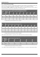
4.8.2 Gas Line Sizing Tables for LP GAS
For your convenience, see below an excerpt from gas line sizing tables for a single LP appliance. Their intended use is for pipe sizing
between the 2nd stage (low pressure) regulator and the appliance. For details, see the current NFPA 54 or NFPA 58.
Required input for 160000 / 199000 BTU/hr for the RTG-L-160/199N/X1. The gas supply system must be sized for the combined
total maximum BTU/hr load requirements of all gas appliances running simultaneously.
Table 14 Maximum capacity of the gas supply pipe in thousands of BTU per hour of Undiluted LP Gas at 11" W.C (0.4 psig or
27.4mbar) based on a pressure drop of 0.5" W.C (1.25mbar).
Table 15 Maximum capacity in thousands of BTU of the gas supply pipe per hour of Undiluted LP Gas at 11" W.C (0.4 psig or
27.4mbar) based on a pressure drop of 0.5" W.C (1.25 mbar).
* EHD = Equivalent Hydraulic Diameter. The greater the value of EHD, the greater the gas capacity of the tubing.
Table 16 Maximum capacity in thousands of BTU of the gas supply pipe per hour of Undiluted LP Gas at 11" W.C (0.4 psig or
27.4mbar) based on a pressure drop of 0.5" W.C (1.25 mbar).
* Source National Fuel Gas Code NFPA 54, ANSI Z223.1 - No Additional Allowance is necessary for an ordinary number of fittings.
Pipe Sizing Between Single- or Second-Stage (Low-Pressure) Regulator and Appliance
Nominal
Iron
Pipe inches
Internal
Diameter
inches
Length of Black Iron Pipe (Schedule 40 Metallic Pipe), Feet
10 20 30 40 50 60 80 100
1/2 0.622 291 200 160 137 122 110 101 94
3/4 0.824 608 418 336 287 255 231 212 197
1 1.049 1150 787 632 541 480 434 400 372
CSST Sizing Between Single- or Second-Stage (Low-Pressure) Regulator and Appliance Shutoff Valve
EHD* Length of Corrugated Stainless Steel Tubing (CSST), Feet
10 20 30 40 50 60 70 80 90 100
23 254 183 151 131 118 107 99 94 90 85
25 303 216 177 153 137 126 117 109 102 98
30 521 365 297 256 227 207 191 178 169 159
31 605 425 344 297 265 241 222 208 197 186
Tube Sizing Between Single- or Second-Stage (Low-Pressure) Regulator and Appliance
Nominal
tube,
inches
Internal
Diameter
inches
Length of Semirigid Copper Tubing, Feet
10 20 30 40 50
1/2 0.527 188 129 104 89 79
5/8 0.652 329 226 182 155 138