Installation and Operation instructions Infiniti Tankless® L-Series INDOOR MODEL WARNING! Improper installation, adjustment, alteration, service or maintenance can cause injury or property damage. Refer to this manual. For assistance or additional information consult a qualified installer, service agency or the gas supplier. NOTICE Upon completion of the installation, these instructions should be handed to the user of the appliance for future reference.
Table of contents Table of contents 1 Key to symbols and safety instructions . . . . . . . . . . . . .3 1.1 Key to symbols . . . . . . . . . . . . . . . . . . . . . . . . . . . . . .3 1.2 Safety instructions. . . . . . . . . . . . . . . . . . . . . . . . . . .3 2 Safety information. . . . . . . . . . . . . . . . . . . . . . . . . . . . . . .8 3 Appliance details . . . . . . . . . . . . . . . . . . . . . . . . . . . . . . . .9 3.1 Features . . . . . . . . . . . . . . . . . . . . . . . . . . . . . . . . . .
Key to symbols and safety instructions 1.2 1 Key to symbols and safety instructions 1.1 Key to symbols Warnings In warnings, signal words at the beginning of a warning are used to indicate the type and seriousness of the ensuing risk if measures for minimising danger are not taken. The following signal words are defined and can be used in this document: DANGER: DANGER indicates a hazardous situation which, if not avoided, will result in death or serious injury.
Key to symbols and safety instructions H CAUTION: ▶ To ensure that the water heater functions properly, follow these installation and maintenance instructions. ▶ Never close the blow-off line of the pressure safety valve. For safety reasons, water may escape during heating. H DANGER: Risk of explosion! If you smell gas, ▶ Turn off the gas shut-off valve. ▶ Open windows and doors. ▶ Do not try to light the appliance. ▶ Do not touch any electrical switch, telephone, and do not use outlets.
Key to symbols and safety instructions ▶ Installation, gas and flue connection, initial commissioning, electrical connections and annual maintenance must only be carried out by a trained and certified installer. H CAUTION: Combustion air. ▶ Keep the combustion air free of corrosive substances (halogenated hydrocarbons that contain chlorine or fluorine compounds). H WARNING: Never shut off safety valves! ▶ Water may escape from the safety valve at any time when the water is being heated.
Key to symbols and safety instructions ▶ If the building has occupants in the above groups who operate hot water faucets, or state laws / local ordinances stipulate specific water temperatures, take the following precautions: – Use the lowest possible temperature setting. – To prevent scalding, install a tempering device, such as an automatic mixing valve, at hot water tap or water heater.
Key to symbols and safety instructions NOTICE: DANGER: Fatal accidents! Carbon monoxide poisoning. ▶ Carefully plan where you install the heater. Correct combustion air supply and flue pipe installation are very important. If a gas appliance is not installed correctly, fatal accidents can result such as carbon monoxide poisoning or fire.
Safety information NOTICE: 2 Safety information Appliance damage! ▶ Label all wires prior to disconnection when servicing controls. Wiring errors can result in improper and dangerous operation. Verify proper operation after servicing. WARNING: Relief valve discharges! ▶ If a relief valve discharges periodically, this may be due to thermal expansion in a closed water supply system. Contact the water supplier or local plumbing inspector on how to correct this situation. Do not plug the relief valve.
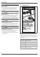
Appliance details 1) Source: Moritz, A.R. and Henriques, F.C., Jr. (1947). Studies of thermal injury. II. The relative importance of time and surface temperature in the causation of cutaneous burns, Am J of Pathol, 23, 695-720. Table 2 Approximate time-temperature relationship until there is a risk of scalding WARNING: CANCER AND REPRODUCTIVE HARM WWW.P65WARNINGS.CA.GOV AS REQUIRED BY THE STATE OF CALIFORNIA PROPOSITION 65.
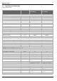
Appliance details 3.2 Specifications (Technical data) Approved in US/Canada Technical characteristics Units Infiniti Tankless® L-Series RTG-L-199N/X1 Infiniti Tankless® L-Series RTG-L-160N/X1 Capacity Maximum flow rate at a 35 °F (19.4 °C) rise1) GPM (l/min) 11.2 (42.4) 9 (34) Maximum flow rate at a 45 °F (25 °C) rise GPM (l/min) 8.7 (32.9) 7(26.7) 5.8 (21.9) Maximum flow rate at a 55 °F (30.6 °C) rise GPM (l/min) 7.2 (27.5) Maximum flow rate at a 75 °F (41.7 °C) rise GPM (l/min) 5.
Appliance details Technical characteristics Units Infiniti Tankless® L-Series RTG-L-199N/X1 Infiniti Tankless® L-Series RTG-L-160N/X1 Net weight pounds (kg) 77.5 (35.2) 73.2 (33.2) Gross weight pounds (kg) 89.95 (40.8) 85.54 (38.8) Electrical Voltage V AC 120 120 Frequency Hz 60 60 Amperage (Idle) mA 40 40 Amperage (operation) A ≤ 2.7 ≤ 2.
Appliance details 3.3 Unpacking the heater The heater is default-set by the manufacturer to operate with Natural Gas; for use with Liquid Propane, follow the conversion instructions in section 6.7.1. Before commissioning the unit be certain you have the heater correctly set for your type of Gas: Propane or Natural Gas. Identification labels are found on the shipping box, and on the rating plate which is located on the left side (when facing appliance front) of the cover.
Appliance details ▶ Slowly open the front cover [1]. Fig. 4 Open front cover ▶ Disconnect the wire from the HMI (display) [2]. ▶ Lift the front cover to remove from the appliance. ▶ Install the appliance so that it hangs vertically. 3.4 General rules to follow for safe operation H Warning: Safety Rules! 1. You must follow these instructions when you install your heater.
Appliance details 6. Keep the water heater area clear and free from combustibles and flammable liquids. Do not locate the heater over any material which might burn. 7. Correct gas pressure is critical for the proper operation of this heater. Gas piping must be sized to provide the required pressure at the maximum output of the heater, while all the other gas appliances are in operation. Check with your local gas supplier, and see the section on connecting the gas supply. See section 4.8 (page 33). 8.
Appliance details 3.5 Fig.
Installation instructions 4.2 Introduction Please follow these instructions. Failure to follow instructions may result in: ▶ Damage or injury. ▶ Improper operation. ▶ Loss of warranty. DANGER: ▶ The water heater must be installed by a qualified installer in accordance with these instructions. If improperly installed, a hazardous condition such as explosion or carbon monoxide poisoning could result. Manufacturer is not responsible for improperly installed appliances.
Installation instructions WARNING: ▶ Flammable materials, gasoline, pressurized containers, or any other items or articles that are potential fire hazards must NOT be placed on or adjacent to the heater. The appliance area must be kept free of all combustible materials, gasoline and other flammable vapors and liquids. WARNING: ▶ Do not install this appliance on a carpeted wall. The heater must be mounted on a wall using appropriate anchoring materials.
Installation instructions CAUTION: Personal injury and property damage. ▶ Appliance must be installed vertically. 4.6 Venting DANGER: Risk of CO poisoning! ▶ Do not reduce the exhaust or combustion air vent pipe sizes. ▶ Do not common vent with any other vented appliance or stove. ▶ Do not use Type-B vent as the actual exhaust vent system for the appliance. DANGER: Flue gas poisoning! Fig.
Installation instructions Flue temperature: ▶ To prevent the risk of flue material overheat the appliance's flue temperature is sensed and is limited. The flue temperature limit is depending on inlet water temperature. ▶ Residential models: Maximum flue temperature is limited to 145 °F (63 °C). 4.6.1 Vent options This appliance can be installed as direct vent or Category IV.
Installation instructions - - 2", 3", and 4" SCH40 (Solid Core) PVC/CPVC 45° long sweep elbow h h 2.5 - - 2", 3", and 4" SCH40 (Solid Core) PVC/CPVC 45° short sweep elbow h h 2.
Equivalent Lengths (Ft.) Vertical 2" PVC Wall Termination Kit 3" PVC Wall Termination Kit Horizontal 081216 081219 Diagram Product description IPEX Manufacturer part number Manufacturer Installation instructions Exhaust: 15 Intake: 7.
Duravent 810009692 (2" x 4") Black PP Vertical Termination Kit - Concentric M&G 810009720 (3" x 5") Black PP Vertical Termination Kit - Concentric 810009693 (2" x 4") Terra-Cotta PP Vertical Termination Kit - Concentric 810009721 (3" x 5") Terra-Cotta PP Vertical Termination Kit - Concentric Equivalent Lengths (Ft.
Installation instructions 4.6.3 Vent specifications 1) Do not exceed the maximum length allowance for either pipe by combining them. CAUTION: Risk of CO poisoning! An improperly sized venting system may lead to undesired effects such as the formation of condensate, gas leakage or spillage. Establish vent clearances that comply with the vent manufacturer's specifications and all applicable national/local codes. Minimum combustion air and exhaust pipe length The minimum exhaust pipe length is 1 foot (0.
Installation instructions Required direct vent terminal clearances (twin pipe / concentric penetration) Fig. 10 Canadian installations1)2) U.S. installations2)3) with direct vent terminals with direct vent terminals A Clearance above grade, veranda, porch, deck or balcony 12 in. (30cm) 12 in. (30cm) B Clearance to window or door that may be opened 36 in. (91cm) 12 in. (30cm) below or to side of opening; 12 in. (30cm) above opening.
Installation instructions Canadian installations1)2) U.S. installations2)3) with direct vent terminals with direct vent terminals I Clearance to service regulator vent outlet 36 in. (91cm) * J Clearance to nonmechanical air supply inlet to building or the combustion air inlet to any other appliance. 36 in. (91cm) 12 in. (30cm) K Clearance to a mechanical air supply inlet 6 feet (1.83m) 36 in. (91cm) above if within 10 ft (3m) horizontally L 7 ft (2.13m)4) * 12 in.
Installation instructions Required other than direct vent terminal clearances (single pipe penetration) Fig. 11 Canadian installations1)2) with non direct vent terminals U.S. installations2)3) with non direct vent terminals A Clearance above grade, veranda, porch, deck or balcony. 12 in. (30cm) 12 in. (30cm) B Clearance to window or door that may be opened. 36 in. (91cm) 48 in. (1.2 m) below or to side of opening; 12 in.
Installation instructions Canadian installations1)2) with non direct vent terminals U.S. installations2)3) with non direct vent terminals J Clearance to nonmechanical air supply inlet to building or the combustion air inlet to any other appliance 36 in. (91cm) 48 in. (1.2m) below or to side of opening; 1 ft (300mm) above opening K Clearance to mechanical air supply inlet 6 ft (1.83 m) 36 in.
Installation instructions 4.6.4 Vent configuration examples for PVC systems Below are approved examples of vertical and horizontal venting installations. NOTICE: Using a single pipe vent in cold climates puts the water heater at risk of freezing, as negative air pressure is common in buildings during cold weather. This situation will pull cold air through the heat exchanger and can lead to damage and a water leak and is not covered by the product's warranty.
Installation instructions Fig. 16 Fig. 15 Horizontal venting installation (combustion air piping not shown) Horizontal venting system (sealed combustion) [1] Intake [2] Exhaust [1] [2] [3] [4] Termination Water heater Elbow Horizontal run should slope ¼" per foot upwards to water heater. [LA] 12 inches (305 mm) (18 in. for Canada) above maximum snow level or at least 24 inches (610 mm), whichever is greater.
Installation instructions With Flex Pipe the maximum length is reduced by 60%, (applies only to the section in flex PP). Example: 10 feet of flex PP is equivalent to 25 feet of rigid PP. Flex Pipe according to the suppliers instructions is for use in the vertical part of the installation only. 4.6.5 Connecting the condensate water drain NOTICE: Risk of condensate pipe freezing! ▶ Do not install condensate drain tubing in areas where it may freeze. Appliance condensate drain installation Fig.
Installation instructions Refer to fig. 23 for preferred installation positions in the vent system. NOTICE: A blocked breather may cause an undesired double-siphon effect. ▶ Ensure that the vacuum relief opening included in the siphon is not obstructed (for example with pipe dope) to allow correct function. Verify condensate disposal/neutralization is in accordance with federal, State, and local regulation. This is a high efficiency appliance, condensate flow can be as much as 2.1 gal/hr at full power.
Installation instructions 4.6.7 Single Pipe Venting NOTICE: ▶ Single pipe venting not recommended in cold climates. ▶ Installations resulting in negative pressure/back draft require sealed combustion (twin pipe / concentric). ▶ Damage caused from back draft, ie. freezing, is not covered by warranty. NOTICE: ▶ When installed in an environment where corrosive chemicals or dirty air (e.g. hair salons, car washes) are present the sealed combustion (twin pipe or concentric) is required.
Installation instructions 4.7 Factory settings The appliances are supplied having been set in the factory for the values shown on the rating plate for natural gas. For any other adjustments see chapter 6.7.1. 4.7.1 Natural gas The appliances must not be operated if the dynamic gas pressure is less than 3.5” WC1) or greater than 10.5” WC. 4.7.2 Liquid propane gas (after gas conversion) The appliances must not be operated if the dynamic gas pressure is less than 8”WC2) or greater than 13” WC.
Installation instructions Fig. 25 [1] [2] [3] [LA] Gas connection Shut off valve Gas supply Cap Minimum 3" sediment trap, (drip leg) Once connections are made, check for gas leaks at all joints. Apply some gas leak detection solution to all gas fittings. Bubbles are a sign of a leak. A combustible gas detector may also be used to detect for leaks. DANGER: Explosion hazard! ▶ If you detect a gas leak, shut off the gas and ventilate the room (open windows, doors).
Installation instructions GAS LINE SIZING The gas supply piping for a single heater should be sized for a maximum draw of 199000 BTU/hr for the RTG-L-199N/X1. Measure the length of the gas supply line from the building's gas main to the heater and use section 4.8.1 and 4.8.2, page 35 or the gas line manufacturer’s sizing tables to determine the pipe diameter necessary.
Installation instructions 4.8.2 Gas Line Sizing Tables for LP GAS For your convenience, see below an excerpt from gas line sizing tables for a single LP appliance. Their intended use is for pipe sizing between the 2nd stage (low pressure) regulator and the appliance. For details, see the current NFPA 54 or NFPA 58. Required input for 160000 / 199000 BTU/hr for the RTG-L-160/199N/X1.
Installation instructions 4.9 Water quality Water quality can have an impact on appliance longevity. Water supplied to the Infiniti Tankless® K-Series must be in accordance with table 17 and fig. 26. For water analysis data call your local water department, or if on a well, have well water analyzed periodically. Heavy scale will form if the combination of water total hardness and pH exceeds the values specified in fig.
Installation instructions NOTICE: ▶ This heater is not approved for preheated water applications exceeding 140 °F (60 °C) for Residential appliances, in these cases a 3-way valve or mixing valve must be installed before the appliance to prevent water exceeding 140 °F (60 °C) from entering the appliance. ▶ When facing the heater, the ¾" cold connection is on the top right and the hot connection is on the top left. ▶ Tighten all water connections with the support of a wrench, see fig. 28. Fig.
Installation instructions 4.11 Domestic hot water recirculation 4.11.2 Recirculation options The following drawings are provided to illustrate two possible recirculation designs. These schematic is for illustration only and must not be used for actual Installation without appropriate engineering and technical advice from a properly licensed professional in the locality where the installation is made.
Installation instructions • Cross Over Mode Cross over mode requires two (2) Grundfos thermal by-pass valves or one (1) AquaMotion AMK-ODR valve. Tank loading This recirculation option gives the option of using one of three temperature sensors to control the recirculation option. The scheduling option is not available for tank loading. • External NTC - 7 736 505 665 – Only compatible with BW cable/sensor accessory (7736504583).
Installation instructions 4.12 Cascading Operation Cascading allows up to twenty four appliances to be connected in parallel. One of the appliances will serve as the controlling primary appliance and will attempt to meet the hot water demand. If the hot water demand is beyond the capacity of the primary appliance, a signal is sent to one or more of the secondary appliances to ignite. A cascading kit must be installed for each secondary appliance included in the installation.
Installation instructions Fig.
Installation instructions Fig.
Electrical connections 4.14 Measuring gas pressure 4.14.1 Gas supply pressure Confirm gas pressure upon installation. Connecting manometer ▶ Shut off gas supply at installer supplied shutoff valve for this water heater. ▶ Locate the inlet gas pressure test port (see Fig. 36). ▶ Loosen the screw inside test port fitting (do not remove) and connect the manometer tube to the test port (see Fig. 36). Fig.
Operation instructions ▶ Check the fuse on the printed circuit board for electrical continuity, see fig. 39, [1]. Fig. 37 Connecting power supply cord [1] Power cord length: 5.9ft (1.8m). Fig. 39 Note: The power supply that the appliance is plugged into should be isolated from possible water damage. Observe proper clearance to avoid damages. [1] Fuse 5.2 Fuse position ▶ After checking the fuses, reinstall all parts in reverse order.
Operation instructions WHAT TO DO IF YOU SMELL GAS 1 DANGER: Risk of explosion! 2 3 8 ▶ ▶ ▶ ▶ ▶ 7 Fig. 41 [1] [2] [3] [4] [5] [6] [7] [8] 6.1 6 5 4 6720817984-51.
Operation instructions NOTICE: Appliance malfunction! ▶ If the problem persists, contact your installer. 6.4 Temperature selection By default, the unit is set for 120 °F (49 °C) outlet water. To select a hot water temperature: ▶ Press the buttons and temperature is displayed. until the desired Fig. 44 Fig. 43 DANGER: To increase setpoint temperature limit of the appliance: ▶ Access the menu LM - temperature Limit ( section 6.5.5).
Operation instructions 6.4.1 Programming the default setpoint temperature ▶ Press buttons menus. or to scroll through the available Available menus Display Description P4 Fig. 45 ▶ Press the buttons to be memorized. ▶ Press the button point temperature. and to select the temperature for 3 seconds to save the default set When the display stops blinking, the default set point temperature is saved in memory. Information (section 6.5.1) P7 Gas Type P9 Purge (section 6.5.
Operation instructions ▶ Press buttons or to choose the following information. – OD (Operation Data) – FH (Failure History) ▶ Press the button to select the desired information. Table 24 Total of cycles OD (Operation Data) In this example, the numbers of cycles is: 4 061 776. Allows you to view various parameters of the current operation of the appliance. ▶ Press buttons or to choose the following information: In the calculation of number of cycles, 1 cycle means 1 ignition.
Operation instructions ▶ Press the button until the display shows P9 (Purge). After 2 sec. the fan starts working to purge the exhaust circuit. The fan remains running until the Purge menu is exited, to do so: ▶ Press the button . 6.5.3 PC (Cascading) Use this menu only after installing the cascading kit (7736502750). ▶ Only a qualified technician can change this parameter. How to choose an option in PC (Cascading), ▶ Press the button to enter PC (Cascading).
Operation instructions A1 Recirculation Program Schedule Choosing a recirculation program: ▶ Press buttons or to scroll through the options. – OF OFF – Hr House Recirculation - It show the available schedules. – tI Tank Loading Internal NTC - Tank loading using the water heater’s inlet water temperature sensor to control the pump. – tE Tank Loading External NTC - Tank loading using the external temperature sensor to control the pump.
Operation instructions 6.5.5 LM (Temperature Limit) 140 °F (60 °C) is the maximum temperature to be defined for residential models. How to select Temperature Limit, Fig. 50 A9 - Units ▶ Access to information / adjustments menu. Display shows SA (Settings). ▶ Press the button until A9 (Units) is in the display. ▶ Press the button . ▶ Press the buttons or to select measurement units, – °C - Metric (l/min) – °F - Imperial (gal/min) ▶ Press the button for 3 secs. to save the selected units.
Operation instructions 6.5.9 Pd - Power derate Default setting is On. ▶ Press the button . The appliance will start the auto calibration of main valve. Display will show water flow rate value X 10 (multiplied by 10) during the process. ▶ Only a qualified technician can change this parameter. 6.5.10 Minimum power and check (P2) Water flow will shut-off. ▶ Wait until indication of calibration completed appears on the screen, the value blinks.
Operation instructions ▶ Press buttons or to confirm gas type according to table 27. ▶ Press for 3 seconds to confirm Gas type. The selected gas type blinks. Gas type Natural Gas Liquid Propane Table 27 Display nA LP NOTICE: ▶ All three flow restrictors and seal must be assembled according to the Fig. 52 and Fig. 53, to ensure correct appliance performance. 6.7.1 Gas conversion from NG to LPG DANGER: Fatal accidents! Before any service or testing in the appliance, ▶ Turn off the appliance.
Maintenance and service ▶ Open a hot water tap and check for gas leak (e.g. use leak detector fluid, like water and soap, over and around the metal plate) and act accordingly. ▶ Place the front cover. ▶ Access service mode by pressing and holding down at the same time, , and for 3 seconds. ▶ Press buttons or until the display shows “P7”. ▶ Press . ▶ Press buttons or to choose LP (LPG). ▶ Press the button for 3 secs. to save your selection. The selected temperature blinks.
Maintenance and service Pressure Relief • • Manually open the pressure relief valve to ensure proper operation. Make sure discharge drains away safely. Inlet Water Filter • Verify the inlet water filter screen is clean and undamaged. The inlet water filter is located on the top of the appliance, at the cold water inlet connection. (See Fig. 29, page 38). Close the installer supplied water shutoff valve, purge the water using discharge drains and remove the brass hex cap holding filter.
Troubleshooting 8. Reconnect the water fittings, refill the condensate trap and return the heater to service when danger of freezing has passed. 7.3 Mineral scale build-up Periodic descaling may be necessary in areas with high mineral content in the water, (see table 17, Water Quality). Scale buildup in the heat exchanger may result in lower flow rates, error codes of AA, E3 and E5 and boiling sounds in the heat exchanger.
Troubleshooting before proceeding to the next. The suggested solutions may require that the cover be taken off. (See fig. 3, page 12). 8.2 Burner does not ignite when hot water is turned ON It is recommended to use “P4 Information” page 48, chapter 6.5.1 as a tool for problem solving. 1. If the display is blank, verify power to outlet. (120VAC/ 60Hz properly grounded circuit required). Verify the heater power supply. Check all wire connections including plugged connectors. 2.
Troubleshooting 8.6 Hot water temperature fluctuates at faucet 1. If the water heater set point temperature is high, mixing at the faucet could deactivate the water heater. The addition of too much cold will overpower hot water flow from the tankless water heater reducing its flow below the activation point. If this slows the flow through the tankless water heater below its deactivation point, it will shut off the burner. The end result is nothing but cold water coming out of the outlet. Consult www.
Troubleshooting 8.10 Manifold gas pressure DANGER: Fatal accidents! When the appliance is operating with the front cover removed: ▶ Do not stand in front of the appliance. ▶ Avoid breathing the combustion flue gases. ▶ Turn off the appliance and install the front cover assembly when adjustments and measurement are complete. The manifold gas pressure measurement is only carried out if it is necessary to confirm the value from the rating plate.
Troubleshooting • • • After installation, the appliance shows repeated unresolved errors ( chapter 9). In Natural Gas installations where energy content is less than 900 BTU/cu ft. After replacement of electronic control unit, fan or gas valve. Improper gas pressure will affect combustion. ▶ Please see chapter 4.14 for more information. 8.11.1 Automatic adjust of Gas/Air flow ▶ Press and hold simultaneously buttons , and for 3 seconds.
Troubleshooting ▶ Verify if power bar level is at middle point, see fig. 59. ▶ Press the buttons or to adjust parameter value if power bar level is out of range.1) Fig. 61 Fig. 59 Power bar middle point ▶ Press the buttons or to adjust parameter value if power bar level is out of range.1) Air adjust - A1 parameter ▶ Press the button for 3 seconds and appliance assumes value. The value flashes as a sign of confirmation. ▶ Press the button to finish the A1 air adjust.
Troubleshooting ▶ Press the buttons or to adjust parameter value if power bar level is out of range.1) ▶ Press the button for 3 seconds and appliance assumes value. The value flashes as a sign of confirmation. ▶ Press button to finish the L2 gas adjust (U1). Parameter D2 ▶ Only a qualified technician can change this parameter. Gas and Air adjustment is complete. 8.11.3 Factory default settings Restore factory values for P1 Max. Power To restore factory values for combustion settings.
Problem solving 9 Problem solving 9.1 Error code diagnostics To remove error code from the display, press and hold on/off button for 3 seconds. Fitting, maintenance and repair must only be carried out by qualified contractors. The following table describes the solutions for possible problems (solutions followed by footnote must only be carried out by qualified contractors). Display Description Solution A0 Water temperature sensor [17] [19] [20] disconnected or damaged.
Problem solving Display Description AA3) Condensing unit flue gases temperature [16] above ▶ Check flue gas temperature sensor. 392 °F (200 °C) and/or flue gases temperature [15] ▶ Check water inlet temperature sensor. above 145 °F (63 °C) at the exhaust sensor [15]. ▶ Descale appliance (section 7.3). 1) Appliance regulates power to protect against overheating. AD Flue blockage detected during startup due to ▶ Reset error (press and hold on/off button for 3 insufficient combustion air.
Problem solving Display Description Solution C8 Main water valve [22] disconnected or damaged. ▶ Check main water valve wire connections.1) If the problem persists: ▶ Replace main water valve and/or wire connections. After valve replacement, proceed with main water valve calibration (section 6.6).1) C9 Barometric pressure sensor fault. ▶ Reset error (press and hold on/off button for 3 seconds). If the problem persists: ▶ Replace electronic control unit (ECU). 1) CA Water flow above 9.2gpm.
Problem solving Display Description Solution E34) Flue gas temperature above 167 °F (75 °C) or 2 minutes above 145 °F (63 °C). Appliance burner cut off to prevent overheating. ▶ Descale appliance ( section 7.3).1) ▶ Reset error (press and hold on/off button for 3 seconds). If the problem persists: ▶ Check sensor resistance [15] (section 11) and replace the sensor if it is not according to specification.
Problem solving Display Description Solution F2 F3 F7 F8 Electronic control unit internal error. ▶ Reset error (press and hold on/off button for 3 seconds). If appliance’s configuration is required: ▶ See section 6.5 to configure appliance (region, power, type and gas type) and perform an automatic combustion adjustment according to the section 8.11. ▶ Replace electronic control unit.1) F9 Gas valve driver internal fault. ▶ Check gas valve wire connections.
Electrical diagram 10 Fig.
Electrical diagram [1] [2] [3] [4] [5] [6] [7] [8] [9] [10] [11] [12] [13] [14] [15] [16] [17] [18] [19] [20] [21] [22] [23] [24] [25] 70 Ionization sensor Fan Ignition electrode Power supply Connection for anti freeze kit Connection for recirculation pump Connection for remote control Gas valve - Modulation Water bypass valve Electrovalve 3 Electrovalve 1 Electrovalve 2 Gas valve - Solenoide safety Thermofuse Water flow sensor Exhaust temperature sensor Exhaust temperature sensor - Between chambers Water
Sensor resistance charts (70) 248 230 212 194 176 158 140 (50) (60) 122 104 86 (20) (30) (40) 50 -4 14 32 -40 TEMPERATURE ºF (ºC) (10) (-40) (-30) (-20) (-10) (0) 1 0.1 10 100 RESISTANCE (KOHM) 6720816948-40.1V 464 428 392 356 320 284 248 212 176 140 104 68 -4 -40 32 (100) (120) (140) (160) (180) (200) (220) (240) (80) (-20) (-40) (0) (20) (40) TEMPERATURE ºF (ºC) Inlet, outlet and heat exchanger water temperature sensors characteristics (60) Fig.
Software main menu structure 12 Software main menu structure Fig.
Interior components diagram and parts list 13 Interior components diagram and parts list 13.1 Interior components Fig.
Interior components diagram and parts list Fig.
Protecting the environment 14 Protecting the environment Packing 15 Installer Checklist to be completed by installer upon installation The packing box may be fully recycled as confirmed by the recycling symbol . Components Many parts in the heater can be fully recycled in the end of the product life. Contact your city authorities for information about the disposal of recyclable products. Saving water resources: ▶ Make sure you close all the taps after any use. Avoid leaving the taps dripping.
Installer Checklist to be completed by installer upon installation Checklist to be completed by installer Condensate drain pitched to a drain or to a condensate pump Condensate protected from freezing Electrical power Yes No 120 VAC with ground 3.2 Gas supply Yes No Chapter Shutoff installed on gas supply line 3.2; 4.8; 4.1 Gas line sized to as needed according to NFPA 54 or CSA B 149 4.6.5 Chapter If an LP conversion is the LP kit installed 4.7.
LIMITED TANKLESS HEATER WARRANTY 16 LIMITED TANKLESS HEATER WARRANTY BRADFORD WHITE CORPORATION LIMITED INFINITI TANKLESSΠ K- or L-SERIES WATER HEATER WARRANTY WHAT DOES THIS LIMITED WARRANTY COVER? This limited warranty covers both the heat exchanger and component parts for leakage or other malfunction caused by defects in materials and/or workmanship. It applies to the original consumer purchaser and to any subsequent owner as long as the heater remains installed at its original place of installation.
LIMITED TANKLESS HEATER WARRANTY LIMITED TANKLESS HEATER WARRANTY (CONTINUED) WHAT WILL WE DO TO CORRECT PROBLEMS? 1. If a defect occurs within the heat exchanger warranty period, we will: Provide a replacement heater of our manufacture, (or at our option) repair any unit, which develops a leak in the heat exchanger within the warranty period. To obtain a replacement, you must forward both the rating plate from the defective unit to us and a copy of the original sales receipt.
LIMITED TANKLESS HEATER WARRANTY RTG-L-199/160N/X1 – 6 721 827 274 (2022/06) 79
Bosch Thermotechnik GmbH Sophienstrasse 30-32 D-35576 Wetzlar www.bosch-thermotechnology.