
Installation / Operation Instruction Manual

50
Troubleshooting
RTG-K-199/160N/X2 – 6 720 813 642 (2022/06)
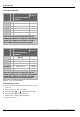
8.12.2 CO
2
and CO values
Table 23 CO & CO target numbers
Table 24 CO & CO target numbers
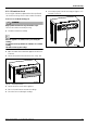
8.12.3 Returning to Service
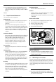
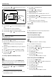
▶ Remove the analyzer probe and place the protection on the
front cover.
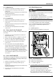
▶ Remove the front cover to access HMI.
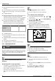
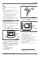
▶ Press the button or until the display shows E.
▶ Press the button to return main menu.
Display shows selected setpoint temperature.
▶ Place the front cover.
CO
2
range (%) Max. CO level
(measured)
Greentherm 9800 SE/SEC O
199 000 BTU
Nat. Gas
max. input P1 8.4 % - 9.0 % < 250 ppm
min. input P2 N/A < 100 ppm
LP Gas
max. input P1 9.7 % - 10.4 % < 250 ppm
min. input P2 N/A < 100 ppm
* Values above are for climate controlled conditions.
Inputs such as gas pressure, heating value of the gas,
humidity and temperature of combustion air all impact CO
and CO
2
values. Changes in these inputs can result in
different CO and CO
2
values on the same appliance.
CO
2
range (%) Max. CO level
(measured)
Greentherm 9800 SE O
160 000 BTU
Nat. Gas
max. input P1 8.5 % - 9.1 % < 250 ppm
min. input P2 N/A < 100 ppm
LP Gas
max. input P1 10.0 % - 10.6 % < 250 ppm
min. input P2 N/A < 100 ppm
* Values above are for climate controlled conditions.
Inputs such as gas pressure, heating value of the gas,
humidity and temperature of combustion air all impact CO
and CO
2
values. Changes in these inputs can result in
different CO and CO
2
values on the same appliance.