
Installation / Operation Instruction Manual

25
Installation instructions
RTG-K-199/160N/X2 – 6 720 813 642 (2022/06)
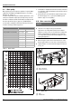
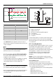
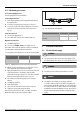
Fig. 17 Pump activation and deactivation thresholds
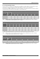
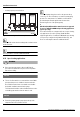
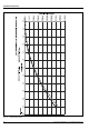
Table 12 RS Menu
The comfort level can be adjusted to achieve the desired
balance between readiness of hot water at the point of use and
energy consumption.
A higher comfort level will result in longer pump run times,
which will consume more electricity and gas.
4.14 Recirculation with the RTG-K-160/199N/X1
Recirculation with the RTG-K-160/199 models requires the
installation of an external pump.
The RTG-K-160/199 models have the capability of controlling
an external pump by switching power ON and OFF to the
external pump using the recirculation pump cable.
Use only bronze or stainless steel pumps. Do not use pumps of
iron construction as they will oxidize and pose health risks.
Refer to pump manufacturers pressure vs flow specifications to
select a pump that will provide adequate flow through the
recirculation system.
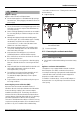
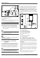
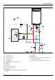
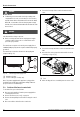
Fig. 18
[1] Cable to control board
[2] Appliance front cover
[3] External recirculation pump (field supplied)
[4] Terminal block
[5] Recirculation pump cable
[6] 5 amp fuse
The flow rate through the recirculation system must be larger
than the activation fl ow rate of the water heater, 0.4 GPM.
A flow rate through the recirculation system greater than 1GPM
is recommended.
4.15 Cascading Operation
Cascading allows up to twenty four appliances to be connected
in parallel. One of the appliances will serve as the controlling
primary appliance and will attempt to meet the hot water
demand. If the hot water demand is beyond the capacity of the
primary appliance, a signal is sent to one or more of the
secondary appliances to ignite. A cascading kit must be
installed for each secondary appliance included in the
installation.
Example: A 7 unit cascade installation includes 1 primary
appliance and 6 secondary appliances. 6 intelligent cascading
kits must be installed for this application.
4.15.1 Plumbing set up
The plumbing should be connected in the reverse return
method with a minimum number of elbows to aid in balancing
pressures between the appliances. Locating the appliances as
close as possible improves performance.
• Follow industry plumbing practices when installing multiple
appliances.
• Minimum pipe diameter: ¾"
• Minimum water pressure: 50 psi
• Maximum distance between appliances: 36"
Comfort level Delta T ( °F)
118
2 16
314
4 12
510
6 8
76
8 4
92
Set point
Adjustable within hidden RS menu (2-18F)
Pump OFF
10F
Pump ON
Water temp in loop (inlet water NTC)
6720817984-46.1V
N
G
L
1
6720817984-47.1V
2
3
5
6
4