
Installation / Operation Instruction Manual

19
Installation instructions
RTG-K-199/160N/X2 – 6 720 813 642 (2022/06)
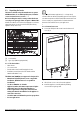
DANGER:
Explosion hazard!
▶DO NOT connect to an unregulated or high pressure
propane line or to a high pressure commercial natural gas
line.
DANGER:
Explosion hazard!
▶ The heater must be isolated from the gas supply piping
system during any pressure testing of that system at test
pressures equal to or more than 0.5 psig (14" W.C.). If
overpressure has occurred, such as through improper
testing of the gas lines or malfunction of the supply system,
the gas valve must be checked for safe operation.
GAS CONNECTIONS
▶ Install a manual gas shut off valve on the gas supply line
within easy reach of the appliance.
▶ Install a union when connecting the gas supply.
▶ Gas connection to the water heater is ¾" NPT. See
chapter 4.8.1 for the minimum internal pipe diameter
required.
▶ Undersized flexible appliance connector is not permitted.
▶ National Fuel Gas Code requires that a sediment trap (drip
leg) be installed on gas appliances not so equipped. The
drip leg must be accessible and not subject to freezing
conditions. Install in accordance with the
recommendations of the serving gas supplier, see fig. 10.
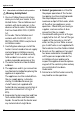
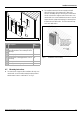
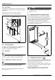
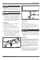
▶ Tighten gas pipe with the support of a wrench, see fig. 9.
Fig. 9 Tighten gas pipe to the heater
Fig. 10 Gas connection
[1] Shut off valve
[2] Gas supply line
[3] Cap
[4] Minimum 3" sediment trap, (drip leg)
Once connections are made, check for gas leaks at all joints.
Apply some gas leak detection solution to all gas fittings.
Bubbles are a sign of a leak. A combustible gas detector may
also be used to detect for leaks.
DANGER:
Explosion hazard!
▶ If you detect a leak, shut off the gas. Tighten appropriate
fittings to stop leak. Turn the gas on and check again with a
gas leak detection solution. Never test for gas leaks using a
match or flame.
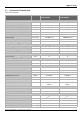
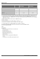
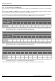
GAS LINE SIZING
The gas supply piping for a single heater should be sized for a
maximum draw of 160 000 BTU/hr /199 000 BTU/hr for the
RTG-K-199/160N/X2. Measure the length of the gas supply line
from the building's gas main to the heater and use
section 4.8.1, page 20 or the gas line manufacturer’s sizing
tables to determine the pipe diameter necessary. If there are
more gas consuming appliances on the line, size the gas line
according to the total maximum BTU input rating for all
appliances combined.
Note: Undersizing the gas line may result in diminished hot
water flow rate and temperature. See chapter 4.17, page 29
for the procedure to measure gas pressure. Proper gas
pressure must be confirmed at time of installation.