
Installation / Operation Instruction Manual


55
Maintenance and service
RTG-K-199/160N/X1 – 6 720 817 984 (2022/06)
DANGER:
▶ Always shut off the electrical power supply, shut off the
manual gas valve and shut off the water valves whenever
servicing.
WARNING:
▶ Replace all dismantled joints and o-rings with new ones.
▶ Consult spare part list at www.bradfordwhite.com.
NOTICE:
▶ Inspect and clean the complete water heating system once
a year.
▶ Follow points 5 and 6 in Table 27 after 400 operation hours
or 25000 cycles (whichever occurs first), see
chapter 6.5.1 (Op. Data).
▶ Inspect the water heater and components for wear or
fatigue. Immediately repair all faults to avoid damage to the
system.
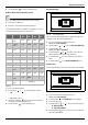
Table 27
7.1 Required annual maintenance
(To remove front cover, see page 12).
Venting System
NOTICE:
Venting system blocked!
▶ For horizontally vented appliances, keep the area around
the venting system free of snow or ice to prevent blockage.
• Venting system - inspect inside of flue pipe for any blockage
or restriction.
• Observe burner flames during heater operation (front
cover must be removed). Burner flames should be steady
and blue. Yellow, inconsistent (bouncing) flames may be an
indication of poor ventilation or combustion air supply.
Inspect the combustion air inlet pipe for blockage or debris.
Inspect combustion air and exhaust terminations for
blockage or debris.
Heat Exchanger
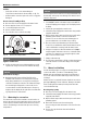
• Inspect burner observation window (Fig. 66) for cracks or
spillage of flue gases. Observe burner flames during heater
operation. Flames should be steady and blue with no signs
of yellowing. Yellow burner flames are an indication of
improper combustion. Refer to Section 4.6, page 18 of this
manual to verify exhaust system and combustion air supply
meets manufacturer's specifications.
Pressure Relief
• Manually open the pressure relief valve to ensure proper
operation.
• Make sure discharge drains away safely.
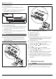
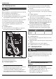
Inlet Water Filter
• Verify the inlet water filter screen is clean and undamaged.
The inlet water filter is located on the top of the appliance,
at the cold water inlet connection. (See Fig. 29, page 38).
Close the installer supplied water shutoff valve, purge the
water using discharge drains and remove the brass hex cap
holding filter. Remove the filter, clean and/or replace if
damaged.
Descaling
• In areas where the water supply has a high mineral content
(see table 17, Water Quality), the heat exchanger should
be flushed with a descaling solution. Scale build up will
shorten the life of the water heater, and damage resulting
from scale is not covered under warranty. Refer to
section 7.3 for detailed instructions on descaling the heat
exchanger.
Condensate siphon
• Check for debris and clean if needed.
Annual maintenance table
Every year
1. Inspect venting system X
2. Inspect combustion chamber X
3. Inspect burner X
1)
1) Proceed with air filter cleaning or replacement if error code
CE, CF and C2 is displayed. Check the flue exhaust for
blockage (appliance is protected against flue blockage).
4. Inspect pressure relief X
5. Inspect water filter X
6. Heat Exchanger Descaling X
2)
2) Proceed with heat exchanger descaling whenever error
codes AA and E5 are displayed (appliance is protected
against over heating in case of scaling, see table 17, Water
Quality).
7. Inspect condensate siphon X
8. Inspect air filter X
1)