
Installation / Operation Instruction Manual

46
Troubleshooting
RTG-K-199/160N/X2 – 6 720 813 642 (2022/06)
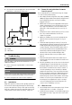
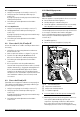
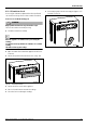
▶ Connect the pressure gauge connection "+" to the test
point [B].
▶ Loosen the shutter screw of the pressure head point [A].
▶ Connect the pressure gauge "-" to the pressure head point
[A].
▶ Turn On the appliance.
▶ Open all hot water faucets to achieve a flow rate of at least
6 gallons per minute. (1 tub and 2 sinks should be
sufficient). If heater goes back to P2, open more hot water
fixtures to allow sufficient flow and access to P1 menu.
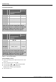
▶Record the manifold gas pressure reading in table 22.
Manifold gas pressure refers to the relative pressure
between gas manifold nozzles inlet and outlet [A]-[B].
Table 22
▶ Turn Off the appliance.
▶ Disconnect the pressure gauges from the pressure heads
points [A] and [B].
▶ Tighten the shutter screws of the pressure heads points [A]
and [B].
▶ Place front cover in the appliance.
▶ Turn ON the appliance to return to normal operation.
8.11 Adjusting Gas/Air flow
DANGER:
Risk of CO poisoning!
Gas air/flow adjustment is performed with the front cover of the
appliance removed. Avoid exposure to exhaust vent gases. Do
not stand in front of the exhaust vent while appliance is
operating.
Appliance is pre-adjusted by default with factory
parameters.
Gas/Air adjustments are only required when;
• The appliance is converted to LPG and energy content is
more than 2820 BTU/cu ft ( chapter 6.7).
• After installation, the appliance shows repeated
unresolved errors ( chapter 9).
• After replacement of electronic control unit, fan or gas
valve.
Improper gas pressure will affect combustion.
▶ Please see chapter 4.17 for more information.
8.11.1 Automatic adjust of Gas/Air flow
▶ Press and hold simultaneously buttons , and
for 3 seconds.
▶ Press the buttons or to select UC (Combustion
Automatic Adjustment) menu.
▶ Press the button to enter UC menu.
Automatic adjustment will begin.
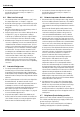
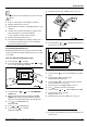
▶ Open hot water faucets when the display shows Tap
Symbol image (1 tub and 2 sinks should be sufficient;
when there is enough water flow the image disappears).
Fig. 45 Combustion Auto Adjust - Open Taps
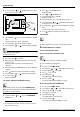
The Combustion Auto Adjust process takes several minutes.
Steps from 1 to 7 will appear on the display.
▶ Do not interfere with the appliance during the auto
adjustment process.
If the display shows “AD” during calibration process,
▶ Press button which will resume the calibration
process.
▶ Wait until display shows DN blinking as a sign of calibration
complete.
▶ Touch the symbol to exit UC menu.
Gas and Air auto adjustment is complete.
Value Date
Manifold gas
pressure