
Installation / Operation Instruction Manual


24
Installation instructions
RTG-K-199/160N/X2 – 6 720 813 642 (2022/06)
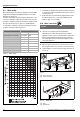
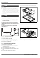
Fig. 15 Appliance drain installation
[1] Condensate drain connection
[2] Breather
Installing an additional breather downstream is not necessary
since this function is already included in the heater.
NOTICE:
A blocked breather will prevent siphon from draining.
▶ Ensure that the vacuum relief opening included in the
siphon is not obstructed (for example with pipe dope) to
allow correct function.
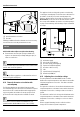
Verify condensate disposal/neutralization is in accordance with
federal, State, and local regulation.
This is a high efficiency appliance; condensate flow can be as
much as 2.1 gal/hr at full power.
4.12 Domestic hot water recirculation with
external pump
The following drawings are provided to illustrate possible
recirculation designs. This schematic is for illustration only and
must not be used for actual installation without appropriate
engineering and technical advice from a properly licensed
professional in the locality where the installation is made.
Recirculation menus for RTG-K-199/160N/X2 are only
available with the Bradford White remote control (TTNR).
This appliance has been designed to permit recirculation by
controlling an external pump. For this function a cable has been
provided to electrically connect the external pump to the
appliance. All the features of recirculation ( section 6.5.4 A1
Recirculation) can be used. Please be aware that the cable
does not provide 120 VAC to operate the recirculation pump, it
is a dry-contact switching external voltage of up to a maximum
of 5 amps.
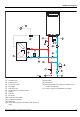
Fig. 16 Recirculation application with a dedicated return line
[1] Cold water supply
[2] Check valve field supplied
[3] Circulator pump (field supplied)
[4] Expansion tank (field supplied)
[5] Circulator cable accessory
[6] PRV
[7] Shutoff valves (field supplied)
[8] RTG-K-199/160N/X2
4.13 Adjusting the recirculation settings
The pump and burner turn ON and OFF based on a delta
between the set point temperature on the water heater and the
inlet water temperature sensor value. This delta is called the
comfort level.
The higher the comfort level, the smaller the delta between the
set point temperature on the water heater and the inlet water
temperature sensor value, resulting in a hotter recirculation
system.
The smaller the comfort level, the larger the delta between the
set point temperature on the water heater and the inlet water
temperature sensor value, resulting in a cooler recirculation
system.
Below is a graph illustrating how the comfort level value
changes the recirculation system’s temperature.