
Installation / Operation Instruction Manual


23
Installation instructions
RTG-K-199/160N/X2 – 6 720 813 642 (2022/06)
WARNING:
Appliance damage!
Appliance will overheat if not filled with water
▶ Ensure that the appliance is filled with water by opening a
hot water faucet, before plugging in the water heater to the
power supply.
▶ The use of unions when connecting water pipes to the inlet
and outlet connections is required. This will facilitate any
necessary servicing.
▶ Plastic or PEX type plumbing line materials are not suitable
for connecting directly to or within an 18" pipe run of the
water heater.
▶ Although water piping throughout the building may be
other than copper, we recommend that copper or suitably
rated stainless steel flex line be used for the water
connections for 1.5’ on either side of the water heater
(follow local codes if more stringent).
▶ Never sweat any piping directly to or beneath the water
connections, as damage will occur to the internal water
valve from heating of the pipe.
▶ Keep water inlet and outlet pipes to no less than ¾"
(19.05mm) diameter to allow the full flow capacity.
▶ If the cold and hot connections to the heater are reversed,
the heater will not function.
▶ Be certain there are no loose particles or dirt in the piping.
Blow out or flush the lines before connecting to the water
heater.
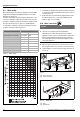
▶ Full port shutoff valves should be installed on both the cold
water supply and hot water outlet lines to facilitate
servicing the heater (see fig. 14).
▶ For installation on a private well system with the use of a
pressure tank, the lowest pressure range setting
recommended is 30 psi (2.06 bar) to ensure optimal
performance.
▶ Proper insulation material should be used in places prone
to freezing conditions.
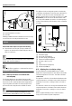
Connecting the pressure relief valve (PRV)
A pressure relief valve must be installed at the time of
installation. No valve is to be placed between the PRV and the
heater. No reducing coupling or other restriction may be
installed in the discharge line. The discharge line must be a
minimum of 4" above a drain and installed such that it allows
complete drainage of both the PRV and the line. The discharge
line must be placed where it will not cause any damage.
The location of the PRV must be readily accessible for servicing
or replacement, and be mounted as close to the water heater as
possible. See fig. 14. To install the PRV, a suitable fitting
connected to an extension on a “T” fitting can be connected to
the hot water line.
▶ Support all piping.
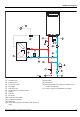
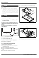
Fig. 14 Plumbing Connections (with shutoff valves) and
Pressure Relief Valve
[1] Pressure relief valve
4.11 Connecting the condensate water drain
NOTICE:
Risk of condensate pipe freezing!
▶ Do not install condensate drain tubing in areas where it may
freeze.
Appliance condensate drain installation
The appliance comes equipped with an internal condensate
drain and siphon. This drains condensation formed in the
secondary heat exchanger. Piping must be installed under the
condensate drain outlet on the water heater and piped for
disposal in accordance with local codes.
To install the condensate drain, connect a ¾"NPT adapter on
the water heater. Use only Teflon tape. Do not block vacuum
relief opening.
6720813642-10.2V
1