
Installation / Operation Instruction Manual

54
Maintenance and service
RTG-K-199/160N/X1 – 6 720 817 984 (2022/06)
▶ Turn Off the appliance.
▶ Remove the front cover from the appliance (section
3.3.2).
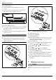
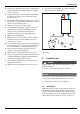
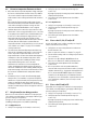
▶ Remove the four screws that retain the cover plate to the
gas manifold, see fig. 51 (plate in grey color).
Fig. 51 Gas manifold
▶ Remove metal plate and seal.
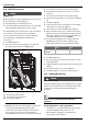
▶ The 3 restrictor plates should be pre-assembled onto their
tray, but if loose in box, follow installation instruction, as
shown in fig. 52 [1].
▶ Insert the LP conversion plate in the appropriate location
shown in Fig. 52 [2].
NOTICE:
▶ All three flow restrictors and seal must be assembled
according to the Fig. 52 and Fig. 53, to ensure correct
appliance performance.
Fig. 52 199kBTU appliance gas conversion kit
Fig. 53 160kBTU appliance gas conversion kit
▶Tighten the four screws.
▶ Open the gas supply valve.
▶ Turn On the appliance.
▶ Open a hot water tap and check for gas leak (e.g. use leak
detector fluid, like water and soap, over and around the
metal plate) and act accordingly.
▶ Place the front cover.
▶ Access service mode by pressing and holding down at the
same time, , and for 3 seconds.
▶ Press buttons or until the display shows “P7”.
▶Press .
▶ Press buttons or to choose LP (LPG).
▶ Press the button for 3 secs. to save your selection.
The selected temperature blinks.
▶ Update “TYPE OF GAS” in the rating plate of the appliance
using the label provided with the gas conversion kit.
▶ Confirm combustion adjustment and, if necessary, adjust
Gas and Air flow parameters, see chapter 8.11 for more
information.
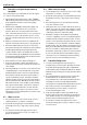
7 Maintenance and service
WARNING:
Maintenance must be done trained or qualified contractor.