
Installation / Operation Instruction Manual

34
Installation instructions
RTG-K-199/160N/X1 – 6 720 817 984 (2022/06)
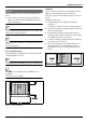
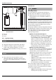
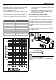
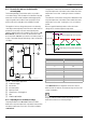
Fig. 25 Gas connection
[1] Shut off valve
[2] Gas supply
[3] Cap
[LA] Minimum 3" sediment trap, (drip leg)
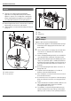
Once connections are made, check for gas leaks at all joints.
Apply some gas leak detection solution to all gas fittings.
Bubbles are a sign of a leak. A combustible gas detector may
also be used to detect for leaks.
DANGER:
Explosion hazard!
▶ If you detect a gas leak, shut off the gas and ventilate the
room (open windows, doors). Tighten appropriate fittings
to stop leak. Turn the gas on and check again with a gas leak
detection solution. Never test for gas leaks using a match or
flame.
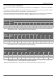
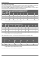
GAS LINE SIZING
The gas supply piping for a single heater should be sized for a
maximum draw of 199000 BTU/hr for the RTG-K-199N/X1.
Measure the length of the gas supply line from the building's gas
main to the heater and use section 4.8.1 and 4.8.2, page 35 or
the gas line manufacturer’s sizing tables to determine the pipe
diameter necessary. If there are more gas appliances on the
line, size the gas line according to the total maximum amount of
BTU draw input rating for all appliances combined.
Note: Undersizing the gas line may result in diminished hot
water flow rate and temperature, or improper appliance
operation (noise and combustion instabilities). See
section 4.16, page 44 for the procedure to measure gas
pressure. Proper gas pressure must be confirmed at time of
installation.