
Installation / Operation Instruction Manual


29
Installation instructions
RTG-K-199/160N/X1 – 6 720 817 984 (2022/06)
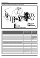
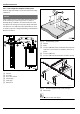
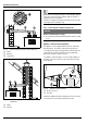
Fig. 15 Horizontal venting installation (combustion air
piping not shown)
[1] Termination
[2] Water heater
[3] Elbow
[4] Horizontal run should slope ¼" per foot upwards to water
heater.
[LA] 12 inches (305 mm) (18 in. for Canada) above maximum
snow level or at least 24 inches (610 mm), whichever is
greater.
NOTICE:
▶ The venting system must be installed in accordance with
the vent system manufacturer’s instructions.
▶ In case vent system manufacturer instructions are not
provided, it is recommended to place pipe supports every
5 feet on horizontal runs, beginning with support near
water heater.
▶ Periodic cleaning of the vent terminal and air-intake
screens is mandatory.
▶ Avoid locating vent terminals near equipment, vegetation,
plants or building features which can be subject to
degradation from exhaust gases.
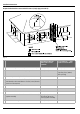
Fig. 16 Horizontal venting system (sealed combustion)
[1] Intake
[2] Exhaust
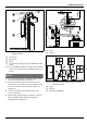
Fig. 17 Vent and combustion air pipe position of a sealed
combustion system
[1] Intake
[2] Exhaust
[X] At least 1foot (305mm)