
Installation / Operation Instruction Manual
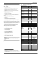
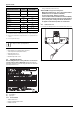
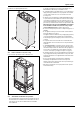
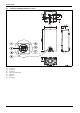
Table Of Contents
- Table of contents
- 1 Key to symbols and safety instructions
- 1.1 Key to symbols
- 1.2 Safety instructions
- 2 FCC rules
- 3 Appliance details
- 4 Installation instructions
- 4.1 Specialized tools
- 4.2 Introduction
- 4.3 Venting
- 4.3.1 Vent material
- 4.3.2 Vent specifications
- Condensate drain requirements
- Twin pipe termination clearances
- Minimum combustion air and exhaust pipe length
- Maximum combustion air and exhaust pipe length
- Use of elbows
- Calculation example for 3" venting:
- Calculation example for 4" venting:
- Required direct vent terminal clearances (twin pipe / concentric penetration)
- Required other than direct vent terminal clearances (single pipe penetration)
- 4.3.3 Vent configuration examples
- 4.3.4 Vent connections
- 4.3.5 Connecting the external condensate water drain
- 4.3.6 Freeze prevention
- 4.3.7 Venting for manufactured (mobile) homes
- 4.3.8 Fan speed adjustment
- 4.4 Combustion air requirements
- 4.5 Proper location for installing your heater
- 4.6 Heater placement and clearances
- 4.7 Hanging appliance on the wall
- 4.8 Mounting installation
- 4.9 Gas piping & connections
- 4.10 Water connections
- 4.11 Water quality
- 4.12 Domestic hot water recirculation
- 4.13 Space heating applications
- 4.14 Measuring gas pressure
- 5 Electrical connections
- 6 Operation instructions
- 7 Maintenance and service
- 8 Troubleshooting
- 9 Problem solving
- 10 Electrical diagram
- 11 Sensor resistance charts
- 12 Functional scheme
- 13 Interior components diagram and parts list
- 14 Protecting the environment
- 15 LIMITED TANKLESS HEATER WARRANTY
- 16 Installer Checklist to be completed by installer upon installation

Appliance details
RTG 199 ME – 6 720 811 615 (2014/05)
8
Safety devices
• Flame failure device (ionization flame rod sensor)
• Overheat prevention (temperature limiter)
• Inlet temperature sensor
• Outlet temperature sensor
• Back flow temperature sensor
3.3 Unpacking the heater
Before installing the unit, be certain you have the correct heater for
your type of Gas - Propane or Natural Gas. Identification labels are
found on the shipping box, and on the rating plate which is located on the
right side panel of the cover.
Fig. 2 Rating plate
[A] Serial number
[B] Type of gas
3.3.1 The box includes
• Tankless water heater
• Bracket for wall hanging the heater
• Installation manual
• Energy Guide label (in the front cover)
The RTG 199ME is not approved or designed for:
• Manufactured (mobile) homes, boats or any mobile installation.
(Modular homes are acceptable for installation).
• Use above 8000 ft A.S.L. altitude (see page 22).
• Outdoor installation without installation of Outdoor kit (BTOK).
• Applications where inlet water temperature is higher than 140°F
(60°C). A 3-way valve or mixing valve must be installed before
the appliance if inlet water temperature exceeds this limit.
3.3.2 Remove front cover
▶ Loosen the two Phillips head screws located on bottom rear of cover.
Fig. 3 Loosen the two screws
Natural Gas
LP Gas
Voltage
Nominal V AC 120
Frequency Hz 60
Amperage
Idle mA 40
Operation A 2.5
Noise db (A) 45 - 65
Water protection
3)
IP X4D
1) To measure Gas Pressure, see Measuring Gas Pressure, chapter 4.14, page 32.
2) Activation varies with inlet water temperatures from 0.5 - 1.6 gallon/minute (1.9
- 6.1 l/m).
3) Protection against water drops.
If appliance is installed at elevations above 2000ft, refer
to chapter 4.3.8 Fan speed adjustment.
Technical characteristics Units RTG 199 ME
Table 3