
Installation / Operation Instruction Manual
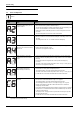
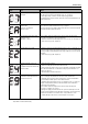
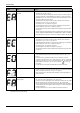
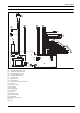
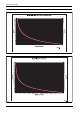
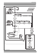
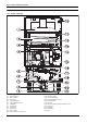
Table Of Contents
- Table of contents
- 1 Key to symbols and safety instructions
- 1.1 Key to symbols
- 1.2 Safety instructions
- 2 FCC rules
- 3 Appliance details
- 4 Installation instructions
- 4.1 Specialized tools
- 4.2 Introduction
- 4.3 Venting
- 4.3.1 Vent material
- 4.3.2 Vent specifications
- Condensate drain requirements
- Twin pipe termination clearances
- Minimum combustion air and exhaust pipe length
- Maximum combustion air and exhaust pipe length
- Use of elbows
- Calculation example for 3" venting:
- Calculation example for 4" venting:
- Required direct vent terminal clearances (twin pipe / concentric penetration)
- Required other than direct vent terminal clearances (single pipe penetration)
- 4.3.3 Vent configuration examples
- 4.3.4 Vent connections
- 4.3.5 Connecting the external condensate water drain
- 4.3.6 Freeze prevention
- 4.3.7 Venting for manufactured (mobile) homes
- 4.3.8 Fan speed adjustment
- 4.4 Combustion air requirements
- 4.5 Proper location for installing your heater
- 4.6 Heater placement and clearances
- 4.7 Hanging appliance on the wall
- 4.8 Mounting installation
- 4.9 Gas piping & connections
- 4.10 Water connections
- 4.11 Water quality
- 4.12 Domestic hot water recirculation
- 4.13 Space heating applications
- 4.14 Measuring gas pressure
- 5 Electrical connections
- 6 Operation instructions
- 7 Maintenance and service
- 8 Troubleshooting
- 9 Problem solving
- 10 Electrical diagram
- 11 Sensor resistance charts
- 12 Functional scheme
- 13 Interior components diagram and parts list
- 14 Protecting the environment
- 15 LIMITED TANKLESS HEATER WARRANTY
- 16 Installer Checklist to be completed by installer upon installation

Problem solving
RTG 199 ME – 6 720 811 615 (2014/05)
46
No flame ionization detected with
water flow.
1. Verify that all manual gas shut off valves are open.
2. Check gas type. See fig. 2, page 8.
3. Reset error code and open a water tap to cycle the heater in an effort to purge air.
Cycling hot water tap on and off multiple times may be necessary. If heater still
faults with EA error code, have a licensed gas technician properly purge air out of
the gas line leading to the water heater.
4. Check three wire connections to ignition group on the lower front of the heat
exchanger are secure, see fig. 73, #7, page 53.
5. Check gas pressure. See chapter 4.14, page 32.
6. Check venting specifications are met. Improper venting may cause premature
failure of the flame sensor rod. See chapter 4.3, page 11.
7. Check that the minimum power fan speed has been adjusted to the proper value.
See page 22.
8. Observe inside the viewing window of the heat exchanger when a hot water tap is
opened. Sparking should be followed by a steady blue flame. If flame is unstable/
yellow with proper gas pressure, confirm CO2 readings per chapter 7.4, page 38.
Ionization failure during operation. 1. Check gas type, fig. 2, page 8.
2. Check three wire connections to ignition group on the lower front of the heat
exchanger are secure, see fig. 73, #7, page 53.
3. Verify that venting specifications are met. Improper venting may cause premature
failure of the flame sensor rod. See chapter 4.3, page 11.
4. Check gas pressure. See chapter 4.14, page 32.
5. Check and adjust CO2 readings. See chapter 7.4, page 38.
6. Check that the minimum power fan speed has been adjusted to the proper value.
See page 22.
Internal hardware/software failure. 1. Disconnect power supply cord and check the two wire and ground connections on
control board as well as ground connection on heater chassis, see fig. 77, #5,
page 57.
2. Pressing the wrong combination of buttons on the control unit can create
confusion among the microprocessors inside. In this case, the error code should
not happen more than once or twice. Turn off the water heater. Turn water heater
back on and try resetting error code. Use the reset button ( ) to reset any
error codes.
3. Possible defective control unit call manufacturer for further instructions.
Ionization error at standby. 1. Loose connection to the flame ionization rod. Verify that the thinner wire leading
from the control unit is securely connected to the set of electrodes located on the
lower front of the heat exchanger, see fig. 73, #7, page 53.
2. Flame ionization rod or control unit may be damaged. Contact manufacturer for
further instruction.
Gas leakage error, gas valve circuit not
closing properly.
1. Disconnect power supply cord and check wire connections on gas valve and the
two connectors on the control board, see fig. 75, page 55.
2. Flow water out of a hot water tap above the minimum activation point of 0.5 GPM.
Measure voltage at the gas valve wire plug connection. The voltage should
measure 24VDC between the left pair of wires and 24VDC between the right pair
of wires when the unit is operating. If voltage is not proper, contact manufacturer
for further instruction.
3. Gas valve may be defective, contact manufacturer for further instruction.
Display Cause Solution
Table 41
* By installer or service technician only.