
Installation / Operation Instruction Manual
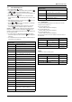
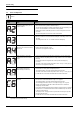
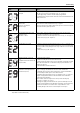
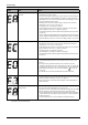
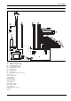
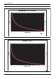
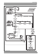
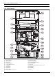
Table Of Contents
- Table of contents
- 1 Key to symbols and safety instructions
- 1.1 Key to symbols
- 1.2 Safety instructions
- 2 FCC rules
- 3 Appliance details
- 4 Installation instructions
- 4.1 Specialized tools
- 4.2 Introduction
- 4.3 Venting
- 4.3.1 Vent material
- 4.3.2 Vent specifications
- Condensate drain requirements
- Twin pipe termination clearances
- Minimum combustion air and exhaust pipe length
- Maximum combustion air and exhaust pipe length
- Use of elbows
- Calculation example for 3" venting:
- Calculation example for 4" venting:
- Required direct vent terminal clearances (twin pipe / concentric penetration)
- Required other than direct vent terminal clearances (single pipe penetration)
- 4.3.3 Vent configuration examples
- 4.3.4 Vent connections
- 4.3.5 Connecting the external condensate water drain
- 4.3.6 Freeze prevention
- 4.3.7 Venting for manufactured (mobile) homes
- 4.3.8 Fan speed adjustment
- 4.4 Combustion air requirements
- 4.5 Proper location for installing your heater
- 4.6 Heater placement and clearances
- 4.7 Hanging appliance on the wall
- 4.8 Mounting installation
- 4.9 Gas piping & connections
- 4.10 Water connections
- 4.11 Water quality
- 4.12 Domestic hot water recirculation
- 4.13 Space heating applications
- 4.14 Measuring gas pressure
- 5 Electrical connections
- 6 Operation instructions
- 7 Maintenance and service
- 8 Troubleshooting
- 9 Problem solving
- 10 Electrical diagram
- 11 Sensor resistance charts
- 12 Functional scheme
- 13 Interior components diagram and parts list
- 14 Protecting the environment
- 15 LIMITED TANKLESS HEATER WARRANTY
- 16 Installer Checklist to be completed by installer upon installation

Maintenance and service
RTG 199 ME – 6 720 811 615 (2014/05)
41
7.6 Control board diagnostics
1. Press ON/OFF button into ON.
2. Immediately following, press and hold simultaneously buttons
or and for 3 seconds, until display reads P2.
3. Press to enter P2 adjustment. The current setting will appear on
the display. If not, repeat process.
4. Press and release the button on the control panel until the
display reads 'P4'. You are now in the diagnostic mode of the control
board.
5. When the display reads 'P4', press and release the button once
again and the display should read 'E'.
6. Use the and button on the control board to cycle through
different diagnostic modes available.
7. Once in the selected diagnostic mode of your choice, press and
release the button to display the diagnostic information.
EXAMPLE: to read the flow rate in gallons per minute while the unit is
flowing water, cycle to the '3d' mode and press the button. A
reading of 25 on the display would indicate the heater is reading a flow
rate of 2.5 gallons/minute.
8. Once the information is obtained, press the button again to
return to the diagnostic mode menu and scroll to addition diagnostic
information.
9. Press ON/OFF button to turn OFF the appliance and back ON again to
return heater to normal function.
7.6.1 Working hours
To see how many hours the appliance has worked, please enter the
“Diagnostic menu” (chapter 7.6);
▶ Select the sub-mode “H0”.
Write the number that shows in the display.
▶ Select the sub-mode “H1”.
Write the number that shows in the display.
▶ Select the sub-mode “H2”.
Write the number that shows in the display.
After checking the sub-modes H0, H1 and H2, introduce the values in
the table below;
Example:
Calculation of number of working hours,
Diagnostic menu
E Entry/Exit into sub-modes
0d Heat exchanger water temperature
1d Inlet water temperature (°F)
2d Outlet water temperature (°F)
3d Water flow (gallons/min)
4d Bypass control monitor (°F) [0d - 2d]
5d Fan speed (Hz)
6d Burner power (%)
7d Maximum power (kW)
8d Back flow temperature (°C)
9d Exhaust temperature (°C)
1F Most recent error/failure
2F 2nd most recent error
3F 3rd most recent error
4F 4th most recent error
5F 5th most recent error
6F 6th most recent error
7F 7th most recent error
8F 8th most recent error
9F 9th most recent error
10F 10th most recent error
1P* Appliance type - Cd (Condensing)
Appliance type - nC (Non condensing)
2P* Appliance power - 175 / 199 (kBTU/hr)
Table 38 * Settings define from factory
+
P
P
P
+
+
P
P
P
3P* Temperature range - H (100-140°F)
Temperature range - C (100-184°F)
H0 Numbers of hours - mode 0
H1 Numbers of hours - mode 1
H2 Numbers of hours - mode 2
Working hours
Number in H0 ______ _______ +
Number in H1 ______ (X 100) = _______ +
Number in H2 ______ (X 10 000) = _______
(H0 + H1 + H2) = Total of hours __________
Table 39
Working hours
Number in H0 60 60 +
Number in H1 5 (X 100) = 500 +
Number in H2 0 (X 10 000) = 0
(H0 + H1 + H2) = Total of hours 560
Table 40
Diagnostic menu
Table 38 * Settings define from factory