
Installation / Operation Instruction Manual
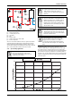
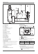
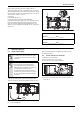
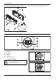
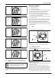
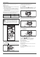
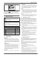
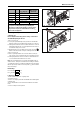

Table Of Contents
- Table of contents
- 1 Key to symbols and safety instructions
- 1.1 Key to symbols
- 1.2 Safety instructions
- 2 FCC rules
- 3 Appliance details
- 4 Installation instructions
- 4.1 Specialized tools
- 4.2 Introduction
- 4.3 Venting
- 4.3.1 Vent material
- 4.3.2 Vent specifications
- Condensate drain requirements
- Twin pipe termination clearances
- Minimum combustion air and exhaust pipe length
- Maximum combustion air and exhaust pipe length
- Use of elbows
- Calculation example for 3" venting:
- Calculation example for 4" venting:
- Required direct vent terminal clearances (twin pipe / concentric penetration)
- Required other than direct vent terminal clearances (single pipe penetration)
- 4.3.3 Vent configuration examples
- 4.3.4 Vent connections
- 4.3.5 Connecting the external condensate water drain
- 4.3.6 Freeze prevention
- 4.3.7 Venting for manufactured (mobile) homes
- 4.3.8 Fan speed adjustment
- 4.4 Combustion air requirements
- 4.5 Proper location for installing your heater
- 4.6 Heater placement and clearances
- 4.7 Hanging appliance on the wall
- 4.8 Mounting installation
- 4.9 Gas piping & connections
- 4.10 Water connections
- 4.11 Water quality
- 4.12 Domestic hot water recirculation
- 4.13 Space heating applications
- 4.14 Measuring gas pressure
- 5 Electrical connections
- 6 Operation instructions
- 7 Maintenance and service
- 8 Troubleshooting
- 9 Problem solving
- 10 Electrical diagram
- 11 Sensor resistance charts
- 12 Functional scheme
- 13 Interior components diagram and parts list
- 14 Protecting the environment
- 15 LIMITED TANKLESS HEATER WARRANTY
- 16 Installer Checklist to be completed by installer upon installation

Maintenance and service
RTG 199 ME – 6 720 811 615 (2014/05)
39
C. Adjusting CO
2
:
Note: P1 adjustment will change the P2 reading. Confirm the P1
value BEFORE adjusting the P2 level.
1. If P1 CO
2
level is off:
▶ Loosen yellow painted Phillips screw (1) and cover should rotate
down (2) revealing a recessed brass slotted screw. Fig.64, page 39.
▶ Turning the slotted screw counter clockwise will raise P1 CO
2
levels
and clockwise will lower P1 CO
2
levels. Adjustments to the slotted
screw will also change P2 CO
2
levels.
▶ After bringing the P1 CO2 readings in proper range, press the
button to enter the P2 mode. Verify CO
2
readings in P2 mode.
2. If P2 CO
2
level is off:
▶ Remove yellow painted #40 Torx cover from the front of the gas
valve. (Fig.65, page 39) A plastic #40 Torx screw will be revealed.
▶ Turning the plastic #40 Torx screw counter clockwise will lower P2
CO
2
levels and clockwise will raise P2 CO
2
levels.
Note: This screw adjustment is very sensitive and should be made in
small increments. It may take several minutes for readings to stabilize.
3. Verify both P1 and P2 CO
2
readings are within the ranges specified in
table36. Repeat steps 1 and 2 as necessary until CO
2
values are within
the specified ranges.
Final Readings
P1 CO
2
Reading: % CO
2
P2 CO
2
Reading: % CO
2
D. Returning to Service:
1. Return slotted screw cover to original position.
2. Reinstall Torx cover.
3. Remove CO
2
analyzer probe and reinstall flathead screw with gasket
in exhaust collar.
4. Press ON/OFF button to turn OFF the heater and then turn ON the
heater.
5. Heater is ready for normal operation.
Fig. 64 Adjusting P1 CO
2
level
Fig. 65 Adjusting P2 CO
2
level
CO
2
range (%)
Max. CO level
(measured)
Nat. Gas
max. input P1 6.3 % - 6.9 % < 250 ppm
min. input P2 2.3 % - 2.6 % < 60 ppm
LP Gas
max. input P1 8.7 % - 9.3 % < 250 ppm
min. input P2 2.7 % - 3.0 % < 60 ppm
* Values above are for climate controlled conditions. Inputs such
as gas pressure, heating value of the gas, humidity and
temperature of combustion air all impact CO and CO
2
values.
Changes in these inputs can result in different CO and CO
2
values on the same appliance.
Table 36 CO
2
& CO target numbers
+