
Installation / Operation Instruction Manual
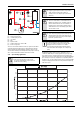
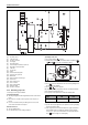
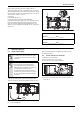
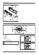
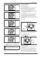
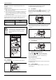
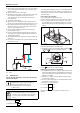

Table Of Contents
- Table of contents
- 1 Key to symbols and safety instructions
- 1.1 Key to symbols
- 1.2 Safety instructions
- 2 FCC rules
- 3 Appliance details
- 4 Installation instructions
- 4.1 Specialized tools
- 4.2 Introduction
- 4.3 Venting
- 4.3.1 Vent material
- 4.3.2 Vent specifications
- Condensate drain requirements
- Twin pipe termination clearances
- Minimum combustion air and exhaust pipe length
- Maximum combustion air and exhaust pipe length
- Use of elbows
- Calculation example for 3" venting:
- Calculation example for 4" venting:
- Required direct vent terminal clearances (twin pipe / concentric penetration)
- Required other than direct vent terminal clearances (single pipe penetration)
- 4.3.3 Vent configuration examples
- 4.3.4 Vent connections
- 4.3.5 Connecting the external condensate water drain
- 4.3.6 Freeze prevention
- 4.3.7 Venting for manufactured (mobile) homes
- 4.3.8 Fan speed adjustment
- 4.4 Combustion air requirements
- 4.5 Proper location for installing your heater
- 4.6 Heater placement and clearances
- 4.7 Hanging appliance on the wall
- 4.8 Mounting installation
- 4.9 Gas piping & connections
- 4.10 Water connections
- 4.11 Water quality
- 4.12 Domestic hot water recirculation
- 4.13 Space heating applications
- 4.14 Measuring gas pressure
- 5 Electrical connections
- 6 Operation instructions
- 7 Maintenance and service
- 8 Troubleshooting
- 9 Problem solving
- 10 Electrical diagram
- 11 Sensor resistance charts
- 12 Functional scheme
- 13 Interior components diagram and parts list
- 14 Protecting the environment
- 15 LIMITED TANKLESS HEATER WARRANTY
- 16 Installer Checklist to be completed by installer upon installation

Operation instructions
RTG 199 ME – 6 720 811 615 (2014/05)
36
this symptom, clean fixtures or replace with higher flowing ones if
necessary.
Saving water resources:
▶ Make sure you close all the taps after any use. Avoid leaving the taps
dripping. Repair any leaking tap.
▶ Define the temperature you want, in the appliance or with the remote
control. This way you have the precise water flow needed (mixing
cold water to regulate temperature will increase the water flow with
consequent waste of water).
The water heater will not ignite if inlet water temperature exceeds the set
point temperature less 9 °F (5 °C). In this condition, the solar mode
indicator will show on the LCD display. See fig. 51, page 35.
Fig. 55
6.5 Operation
▶ When a hot water tap is opened, main burner ignites and LCD
displays indication .
Fig. 56
▶ LCD flashes until selected temperature is reached.
▶ Power bar indicates power percentage in use.
6.6 Reset button
If the LCD shows the error symbol do not shut off power or unplug
the heater. Follow instructions below to reset error first.
Record the error code on LCD and consult “Problem solving” chapter
9.1, page 44.
Fig. 57
After following instructions indicated in “Troubleshooting” section,
▶ press reset button firmly in order to return heater to normal
operation.
Fig. 58 Reset button
If the problem persists, contact your installer.
6.7 Program button
Fig. 59 “Program” key
6.7.1 Memorizing selected temperature
▶ Press buttons or to select desired temperature.
▶ Hold “Program” button for 3 seconds to save temperature.
When LCD stops blinking, temperature is saved in memory.
Using “Program” function
In order to select memorized temperature
▶ Press “Program” key.
LCD shows pre-memorized temperature, which is now the hot water
selected temperature.
6.8 Locked condition
This condition is only valid for appliances with one or more remote
controls installed.
Solar mode activation formula Example:
Temp. inlet > Temp. set - 9 °F
(5 °C)
104 °F (40 °C) > 112 °F (44 °C) -
9 °F (5 °C)
Table 34
WARNING: Appliance damage!
▶ In applications where inlet water temperature can
exceed 140°F (60ºC), a thermostatic or mixing valve
must be installed before the appliance to prevent
water exceeding 140°F (60°C) from entering the
appliance.
+