
Installation / Operation Instruction Manual
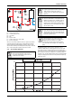
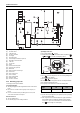
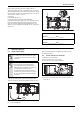
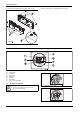
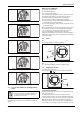
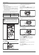
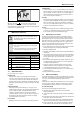
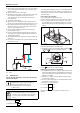
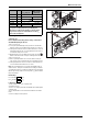

Table Of Contents
- Table of contents
- 1 Key to symbols and safety instructions
- 1.1 Key to symbols
- 1.2 Safety instructions
- 2 FCC rules
- 3 Appliance details
- 4 Installation instructions
- 4.1 Specialized tools
- 4.2 Introduction
- 4.3 Venting
- 4.3.1 Vent material
- 4.3.2 Vent specifications
- Condensate drain requirements
- Twin pipe termination clearances
- Minimum combustion air and exhaust pipe length
- Maximum combustion air and exhaust pipe length
- Use of elbows
- Calculation example for 3" venting:
- Calculation example for 4" venting:
- Required direct vent terminal clearances (twin pipe / concentric penetration)
- Required other than direct vent terminal clearances (single pipe penetration)
- 4.3.3 Vent configuration examples
- 4.3.4 Vent connections
- 4.3.5 Connecting the external condensate water drain
- 4.3.6 Freeze prevention
- 4.3.7 Venting for manufactured (mobile) homes
- 4.3.8 Fan speed adjustment
- 4.4 Combustion air requirements
- 4.5 Proper location for installing your heater
- 4.6 Heater placement and clearances
- 4.7 Hanging appliance on the wall
- 4.8 Mounting installation
- 4.9 Gas piping & connections
- 4.10 Water connections
- 4.11 Water quality
- 4.12 Domestic hot water recirculation
- 4.13 Space heating applications
- 4.14 Measuring gas pressure
- 5 Electrical connections
- 6 Operation instructions
- 7 Maintenance and service
- 8 Troubleshooting
- 9 Problem solving
- 10 Electrical diagram
- 11 Sensor resistance charts
- 12 Functional scheme
- 13 Interior components diagram and parts list
- 14 Protecting the environment
- 15 LIMITED TANKLESS HEATER WARRANTY
- 16 Installer Checklist to be completed by installer upon installation

Installation instructions
RTG 199 ME – 6 720 811 615 (2014/05)
32
Fig. 39 Space heating diagram
[1] Hot water outlet
[2] Cold water inlet
[3] Pressure relief valve
[4] Gas supply
[5] Shut off gas valve
[6] Thermal expansion tank (as required)
[7] Atmospheric vacuum breaker
[8] Cold inlet
[9] Check valve
[10] Pump
[11] Thermostatic mixing valve
[12] Thermometer (optional)
[13] DHW outlet
[14] Water to water heat exchanger
[17] Thermostat
[18] Space heating zone
[19] Zone controller
[20] Space heating pump
[21] Expansion tank
[22] Pressure relief valve
4.14 Measuring gas pressure
Confirm gas pressure upon installation.
Connecting manometer
▶ Shut off gas supply at installer supplied shutoff valve for this water
heater.
▶ Remove front cover and locate inlet gas pressure test port (see
Fig.41).
▶ Loosen screw inside left test point fitting (do not remove) and
connect manometer tube to test point.
Static Pressure Test
▶ Turn gas supply back on.
▶ Record static gas pressure reading in table 33.
Operating Pressure Test
▶ Press ON/OFF button into ON.
▶ Immediately following, press and hold simultaneously buttons
or and for 3 seconds, until display reads P2.
Fig. 40
▶ Press to enter P2 adjustment. The current setting will appear on
the display (factory default).
▶ Press or until P1 appears.
Note: While in this mode the appliance will run constantly at maximum
power and allow maximum water flow.
For inlet gas pressure adjustment consider the following table:
▶ Operate all other gas appliances (except heater) on same gas piping
system at maximum output.
▶ Turn on high volume of hot water flow (at least 6 gpm) (1tub and 2
sinks should be sufficient) and burner will light. If heater display
reverts to P2, open more hot water fixtures to allow sufficient flow.
Press until P1 reappears on the display.
Gas type NG LPG
p
in
3.5” WC 8” WC
Table 32 Minimum inlet gas pressure under full operation
+
P
P
+
+