
Installation / Operation Instruction Manual
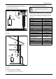
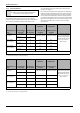
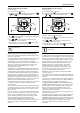
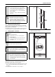
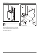
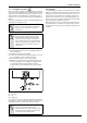
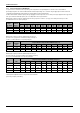
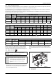
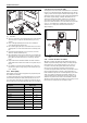
Table Of Contents
- Table of contents
- 1 Key to symbols and safety instructions
- 1.1 Key to symbols
- 1.2 Safety instructions
- 2 FCC rules
- 3 Appliance details
- 4 Installation instructions
- 4.1 Specialized tools
- 4.2 Introduction
- 4.3 Venting
- 4.3.1 Vent material
- 4.3.2 Vent specifications
- Condensate drain requirements
- Twin pipe termination clearances
- Minimum combustion air and exhaust pipe length
- Maximum combustion air and exhaust pipe length
- Use of elbows
- Calculation example for 3" venting:
- Calculation example for 4" venting:
- Required direct vent terminal clearances (twin pipe / concentric penetration)
- Required other than direct vent terminal clearances (single pipe penetration)
- 4.3.3 Vent configuration examples
- 4.3.4 Vent connections
- 4.3.5 Connecting the external condensate water drain
- 4.3.6 Freeze prevention
- 4.3.7 Venting for manufactured (mobile) homes
- 4.3.8 Fan speed adjustment
- 4.4 Combustion air requirements
- 4.5 Proper location for installing your heater
- 4.6 Heater placement and clearances
- 4.7 Hanging appliance on the wall
- 4.8 Mounting installation
- 4.9 Gas piping & connections
- 4.10 Water connections
- 4.11 Water quality
- 4.12 Domestic hot water recirculation
- 4.13 Space heating applications
- 4.14 Measuring gas pressure
- 5 Electrical connections
- 6 Operation instructions
- 7 Maintenance and service
- 8 Troubleshooting
- 9 Problem solving
- 10 Electrical diagram
- 11 Sensor resistance charts
- 12 Functional scheme
- 13 Interior components diagram and parts list
- 14 Protecting the environment
- 15 LIMITED TANKLESS HEATER WARRANTY
- 16 Installer Checklist to be completed by installer upon installation

Installation instructions
RTG 199 ME – 6 720 811 615 (2014/05)
30
Fig. 35 Water filter
[1] Water filter
▶ The use of unions when connecting both water pipes to the inlet and
outlet connections is required. This will facilitate any necessary
servicing.
▶ Plastic or PEX type plumbing line materials are not suitable for
connecting directly to the water heater.
▶ Never sweat any piping directly to or beneath the water connections,
as damage will occur to the internal water valve from heating of the
pipe.
▶ Keep water inlet and outlet pipes to no less than ¾" (19.05mm)
diameter to allow the full flow capacity.
▶ If the cold and hot connections to the heater are reversed, the heater
will not function. Be certain there are no loose particles or dirt in the
piping. Blow out or flush the lines before connecting to the water
heater.
▶ Full port shutoff valves should be installed on both the cold water
supply and hot water outlet lines to facilitate servicing the heater (see
fig. 36).
▶ For installation on a private well system with the use of a pressure
tank, the lowest pressure range setting recommended is 40-60 psi
(2.75 - 4.15bar).
4.11 Water quality
Water quality can have an impact on appliance longevity and may void
the manufacturer's warranty.
For water analysis data call your local water department, or if on a well,
have well water analyzed periodically. If water quality exceeds one or
more of the values specified below, consulting a local water treatment
professional for water softening/conditioning options is recommended.
Connecting the pressure relief valve (PRV)
A listed pressure relief valve must be installed at the time of installation.
No valve is to be placed between the PRV and the heater. No reducing
coupling or other restriction may be installed in the discharge line. The
discharge line must be a minimum of 4” above a drain and installed such
that it allows complete drainage of both the PRV and the line. The
discharge line must be placed where it will not cause any damage.
The location of the PRV must be readily accessible for servicing or
replacement, and be mounted as close to the water heater as possible.
See fig. 36. To install the PRV, a suitable fitting connected to an
extension on a “T” fitting can be sweated to the hot water line.
Support all piping.
Fig. 36 Plumbing Connections (with shutoff valves) and Pressure Relief
Valve
4.12 Domestic hot water recirculation
Although recirculation directly through the tankless water heater is
allowed, temperature stability is improved by recirculating through a
tank as shown in fig. 37. By using the design in fig. 37, there is no
recirculation of hot water through the tankless water heater and
therefore, does not affect the heat exchanger warranty. Direct
recirculation through the tankless water heater is permissible, however,
the heat exchanger warranty is reduced; contact manufacturer for
further installation requirements. The following drawing is provided to
outline one possible recirculation design using the water heater in
conjunction with an Ariston tank water heater. This schematic is for
illustration only and must not be used for actual Installation without
appropriate engineering and technical advice from a properly licensed
professional in the locality where the installation is made.
Description Max. Levels
pH pH 6.5 - 8.5
TDS (total Dissolved Solids) mg/l or ppm 500
Total hardness mg/l or ppm 100 (6 grains)
Aluminum mg/l or ppm 2.0
Chlorides mg/l or ppm 250
Copper mg/l or ppm 1.0
Iron mg/l or ppm 0.3
Manganese mg/l or ppm 0.05
Zinc mg/l or ppm 5.0
Table 31