
Installation / Operation Instruction Manual
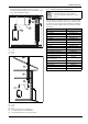
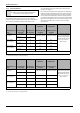
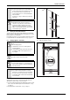
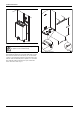
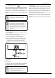
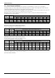
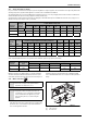
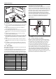
Table Of Contents
- Table of contents
- 1 Key to symbols and safety instructions
- 1.1 Key to symbols
- 1.2 Safety instructions
- 2 FCC rules
- 3 Appliance details
- 4 Installation instructions
- 4.1 Specialized tools
- 4.2 Introduction
- 4.3 Venting
- 4.3.1 Vent material
- 4.3.2 Vent specifications
- Condensate drain requirements
- Twin pipe termination clearances
- Minimum combustion air and exhaust pipe length
- Maximum combustion air and exhaust pipe length
- Use of elbows
- Calculation example for 3" venting:
- Calculation example for 4" venting:
- Required direct vent terminal clearances (twin pipe / concentric penetration)
- Required other than direct vent terminal clearances (single pipe penetration)
- 4.3.3 Vent configuration examples
- 4.3.4 Vent connections
- 4.3.5 Connecting the external condensate water drain
- 4.3.6 Freeze prevention
- 4.3.7 Venting for manufactured (mobile) homes
- 4.3.8 Fan speed adjustment
- 4.4 Combustion air requirements
- 4.5 Proper location for installing your heater
- 4.6 Heater placement and clearances
- 4.7 Hanging appliance on the wall
- 4.8 Mounting installation
- 4.9 Gas piping & connections
- 4.10 Water connections
- 4.11 Water quality
- 4.12 Domestic hot water recirculation
- 4.13 Space heating applications
- 4.14 Measuring gas pressure
- 5 Electrical connections
- 6 Operation instructions
- 7 Maintenance and service
- 8 Troubleshooting
- 9 Problem solving
- 10 Electrical diagram
- 11 Sensor resistance charts
- 12 Functional scheme
- 13 Interior components diagram and parts list
- 14 Protecting the environment
- 15 LIMITED TANKLESS HEATER WARRANTY
- 16 Installer Checklist to be completed by installer upon installation

Installation instructions
RTG 199 ME – 6 720 811 615 (2014/05)
29
4.9.2 Gas Line Sizing Tables for LP GAS
For your convenience see below for an excerpt from gas line sizing tables for a single LP appliance. Their intended use of is for pipe sizing between the
2nd stage (low pressure) regulator and the appliance. For details see the current NFPA 54 or NFPA 58.
Specified pipe lengths are for one RTG 199ME which has a maximum input of 199,000. The gas supply system must be sized for the combined total
maximum BTU/hr load requirements of all gas appliances running simultaneously.
The tables below show the maximum capacity of the gas supply pipe in thousands of BTU per hour of Undiluted LP Gas at 11" W.C (0.4 psig or 27.4
mbar) based on a pressure drop of 0.5" W.C (1.25 mbar).
* EHD = Equivalent Hydraulic Diameter. The greater the value of EHD, the greater the gas capacity of the tubing.
Maximum Capacity of Semi-Rigid (flexible, non corrugated) Tubing in
Thousands of BTU/hr of Undiluted Liquefied Petroleum Gases (at 11
inches Water Column Inlet Pressure).(Based on a Pressure Drop of 0.5
Inch Water Column)* Source National Fuel Gas Code NFPA 54, ANSI
Z223.1 - No Additional Allowance is necessary for an ordinary number of
fittings.
4.10 Water connections
▶ When facing the heater, the ¾ ” cold connection is on the bottom
right and the hot connection is on the bottom left. Centrally locating
the water heater is recommended to keep hot water distribution
times even throughout the structure.
Fig. 34
[1] Cold connection
[2] Hot connection
Nominal Iron
Pipe inches
Internal
Diameter
inches
Length of Black iron Pipe, Feet
10 20 30 40 50 60 80 100
1/2 0.622 291 200 160 137 122 110 101 94
3/4 0.824 608 418 336 287 255 231 212 197
1 1.049 1150 787 632 541 480 434 400 372
Table 28
Tube size,
inches
Length of Corrugated Stainless Steel Tubing (CSST), Feet
EHD* 10 20 30 40 50 60 70 80 90 100
3/4 23 254 183 151 131 118 107 99 94 90 85
3/4 23 303 216 177 153 137 126 117 109 102 98
1 30 521 365 297 256 227 207 191 178 169 159
1 31 605 425 344 297 265 241 222 208 197 186
Table 29
Nominal Iron
Pipe inches
Internal Diameter
inches
Length of Semirigid (soft) Copper ACR Tubing, Feet
10 20 30 40 50
5/8 0.527 188 129 104 89 79
3/4 0.652 329 226 182 155 138
Table 30
NOTICE:
▶ This heater is not approved for preheated water
applications exceeding 140°F (60°C).
NOTICE:
▶ In applications where inlet water temperature can
exceed 140°F (60ºC), a 3-way valve or mixing valve
must be installed before the appliance to prevent
water exceeding 140°F (60°C) from entering the
appliance.