
Installation / Operation Instruction Manual
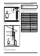
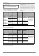
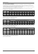
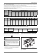
Table Of Contents
- Table of contents
- 1 Key to symbols and safety instructions
- 1.1 Key to symbols
- 1.2 Safety instructions
- 2 FCC rules
- 3 Appliance details
- 4 Installation instructions
- 4.1 Specialized tools
- 4.2 Introduction
- 4.3 Venting
- 4.3.1 Vent material
- 4.3.2 Vent specifications
- Condensate drain requirements
- Twin pipe termination clearances
- Minimum combustion air and exhaust pipe length
- Maximum combustion air and exhaust pipe length
- Use of elbows
- Calculation example for 3" venting:
- Calculation example for 4" venting:
- Required direct vent terminal clearances (twin pipe / concentric penetration)
- Required other than direct vent terminal clearances (single pipe penetration)
- 4.3.3 Vent configuration examples
- 4.3.4 Vent connections
- 4.3.5 Connecting the external condensate water drain
- 4.3.6 Freeze prevention
- 4.3.7 Venting for manufactured (mobile) homes
- 4.3.8 Fan speed adjustment
- 4.4 Combustion air requirements
- 4.5 Proper location for installing your heater
- 4.6 Heater placement and clearances
- 4.7 Hanging appliance on the wall
- 4.8 Mounting installation
- 4.9 Gas piping & connections
- 4.10 Water connections
- 4.11 Water quality
- 4.12 Domestic hot water recirculation
- 4.13 Space heating applications
- 4.14 Measuring gas pressure
- 5 Electrical connections
- 6 Operation instructions
- 7 Maintenance and service
- 8 Troubleshooting
- 9 Problem solving
- 10 Electrical diagram
- 11 Sensor resistance charts
- 12 Functional scheme
- 13 Interior components diagram and parts list
- 14 Protecting the environment
- 15 LIMITED TANKLESS HEATER WARRANTY
- 16 Installer Checklist to be completed by installer upon installation

Installation instructions
RTG 199 ME – 6 720 811 615 (2014/05)
28
4.9.1 Gas Line Sizing Tables for NATURAL GAS
For your convenience see below for an excerpt from gas line sizing tables for a single NG appliance. For details see the current NFPA 54.
Specified pipe lengths are for one RTG 199ME, which has a maximum input rating of 199,000 BTUs. The gas supply system must be sized for the
combined total maximum BTU/hr load requirements of all gas appliances running simultaneously.
The tables below show the maximum capacity of the gas supply pipe in cubic feet per hour. Please contact your local gas supplier for the energy content
of the gas to determine the BTU/hr capacity. Use 1,000 BTU/cubic foot for rough estimations.
Maximum pipe capacity in cubic feet of Natural Gas per hour for gas pressures of 14" W.C. (0.5 psig) or less and a pressure drop of 0.3” W.C.
(0.75mbar) based on 0.60 specific gravity gas).
Maximum pipe capacity in cubic feet of Natural Gas per hour for gas
pressures of <2.0 psig (55" WC or 138 mbar) and a pressure drop of
3.0” W.C. (7.5 mbar) based on 0.60 specific gravity gas).
Maximum pipe capacity in cubic feet of Natural Gas per hour for gas
pressures of 14" W.C. (0.5 psig or 25 mbar) or less and a pressure drop
of 0.5” W.C. (1.25mbar) based on 0.60 specific gravity gas).
* EHD = Equivalent Hydraulic Diameter. The greater the value of EHD, the
greater the gas capacity of the tubing.
Nominal
Iron Pipe
Size, inches
Internal
Diameter
inches
Length of Black iron Pipe (Schedule 40 Metallic Pipe), Feet
10 20 30 40 50 60 70 80 90 100
3/4 0.824 273 188 151 129 114 104 95 89 83 79
1 1.049 514 353 284 243 215 195 179 167 157 148
1-1/4 1.380 1060 726 583 499 442 400 368 343 322 304
1-1/2 1.610 1580 1090 873 747 662 600 552 514 482 455
Table 25
Nominal Iron
Pipe Size,
inches
Internal
Diameter
inches
Minimum Gas Pressure 8.0" WC (20 mbar)
Length of Black Iron Pipe (Schedule 40 Metallic Pipe), Feet
10 20 30 40 50 60 70 80 90 100
1/2 0.622 454 312 250 214 190 172 158 147 138 131
3/4 0.824 949 652 524 448 397 360 331 308 289 273
1 1.049 1787 1228 986 844 748 678 624 580 544 514
Table 26
Tube
size,
inches
EHD*
Length of Corrugated Stainless Steel Tubing (CSST), Feet
10 20 30 40 50 60 70 80 90 100
1 30 330 231 188 162 144 131 121 113 107 101
1 31 383 269 218 188 168 153 141 132 125 118
1 - 1/4 37 639 456 374 325 292 267 248 232 219 208
1 - 1/4 38 746 526 442 386 347 318 295 277 262 249
Table 27