
Installation / Operation Instruction Manual
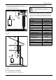
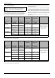
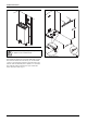
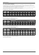
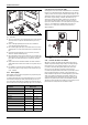
Table Of Contents
- Table of contents
- 1 Key to symbols and safety instructions
- 1.1 Key to symbols
- 1.2 Safety instructions
- 2 FCC rules
- 3 Appliance details
- 4 Installation instructions
- 4.1 Specialized tools
- 4.2 Introduction
- 4.3 Venting
- 4.3.1 Vent material
- 4.3.2 Vent specifications
- Condensate drain requirements
- Twin pipe termination clearances
- Minimum combustion air and exhaust pipe length
- Maximum combustion air and exhaust pipe length
- Use of elbows
- Calculation example for 3" venting:
- Calculation example for 4" venting:
- Required direct vent terminal clearances (twin pipe / concentric penetration)
- Required other than direct vent terminal clearances (single pipe penetration)
- 4.3.3 Vent configuration examples
- 4.3.4 Vent connections
- 4.3.5 Connecting the external condensate water drain
- 4.3.6 Freeze prevention
- 4.3.7 Venting for manufactured (mobile) homes
- 4.3.8 Fan speed adjustment
- 4.4 Combustion air requirements
- 4.5 Proper location for installing your heater
- 4.6 Heater placement and clearances
- 4.7 Hanging appliance on the wall
- 4.8 Mounting installation
- 4.9 Gas piping & connections
- 4.10 Water connections
- 4.11 Water quality
- 4.12 Domestic hot water recirculation
- 4.13 Space heating applications
- 4.14 Measuring gas pressure
- 5 Electrical connections
- 6 Operation instructions
- 7 Maintenance and service
- 8 Troubleshooting
- 9 Problem solving
- 10 Electrical diagram
- 11 Sensor resistance charts
- 12 Functional scheme
- 13 Interior components diagram and parts list
- 14 Protecting the environment
- 15 LIMITED TANKLESS HEATER WARRANTY
- 16 Installer Checklist to be completed by installer upon installation

Installation instructions
RTG 199 ME – 6 720 811 615 (2014/05)
27
4.9 Gas piping & connections
Before connecting the gas supply, check the rating plate on the right side
of the heater to be sure that the heater is rated for the same gas to which
it will be connected. Example rating plate can be found in fig. 2, page 8.
In the United States: The installation must conform with local codes or,
in the absence of local codes, the National Fuel Gas Code ANSI Z223.1/
NFPA 54.
In Canada: The Installation must conform to CGA B149 INSTALLATION
CODES and/or local installation codes.
GAS CONNECTIONS
▶ Install a manual gas shut off valve on the gas supply line within easy
reach of the appliance.
▶ Install a union when connecting gas supply.
▶ The minimum internal diameter required for any appliance connector
is ¾ ”, see chapter 4.9.1 for more details on pipe sizing.
▶ Undersized flexible appliance connector not permitted.
▶ National Fuel Gas Code requires that a sediment trap (drip leg) be
installed on gas appliances not so equipped. The drip leg must be
accessible and not subject to freezing conditions. Install in
accordance with the recommendations of the serving gas supplier,
see fig. 2.
Fig. 33 Gas connection
[1] Gas supply
[2] Cap
[LA] Minimum 3"
Once connections are made, check for gas leaks at all joints. Apply some
gas leak detection solution to all gas fittings. Bubbles are a sign of a leak.
A combustible gas detector may also be used to detect for leaks.
GAS LINE SIZING
The gas supply piping for a single heater should be sized for a maximum
draw of 199,000 BTU/hr. Measure the length of gas supply line from the
building's gas main to the heater and use the chapter 4.9.1 and 4.9.2,
page 28 or the gas line manufacturer’s sizing tables to determine the
pipe diameter necessary. If there are more gas drawing appliances on
the line, size the gas line according to the total maximum amount of BTU
draw input rating of for all appliances combined.
Note: Undersizing the gas line may result in diminished hot water flow
rate and temperature. See chapter 4.14, page 32 for the procedure to
measure gas pressure. Proper gas pressure must be confirmed at time of
installation.
DANGER: Explosion hazard!
▶ DO NOT connect to an unregulated or high pressure
propane line or to a high pressure commercial
natural gas line.
DANGER: Explosion hazard!
▶ The heater must be isolated from the gas supply
piping system during any pressure testing of that
system at test pressures equal to or more than 0.5
psig. If overpressure has occurred, such as through
improper testing of the gas lines or malfunction of the
supply system, the gas valve must be checked for
safe operation.
DANGER: Explosion hazard!
▶ If you detect a leak, shut off the gas. Tighten
appropriate fittings to stop leak. Turn the gas on and
check again with a gas leak detection solution. Never
test for gas leaks using a match or flame.