
Installation / Operation Instruction Manual
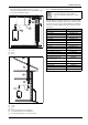
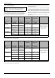
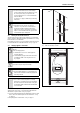
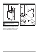
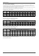
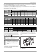
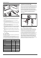
Table Of Contents
- Table of contents
- 1 Key to symbols and safety instructions
- 1.1 Key to symbols
- 1.2 Safety instructions
- 2 FCC rules
- 3 Appliance details
- 4 Installation instructions
- 4.1 Specialized tools
- 4.2 Introduction
- 4.3 Venting
- 4.3.1 Vent material
- 4.3.2 Vent specifications
- Condensate drain requirements
- Twin pipe termination clearances
- Minimum combustion air and exhaust pipe length
- Maximum combustion air and exhaust pipe length
- Use of elbows
- Calculation example for 3" venting:
- Calculation example for 4" venting:
- Required direct vent terminal clearances (twin pipe / concentric penetration)
- Required other than direct vent terminal clearances (single pipe penetration)
- 4.3.3 Vent configuration examples
- 4.3.4 Vent connections
- 4.3.5 Connecting the external condensate water drain
- 4.3.6 Freeze prevention
- 4.3.7 Venting for manufactured (mobile) homes
- 4.3.8 Fan speed adjustment
- 4.4 Combustion air requirements
- 4.5 Proper location for installing your heater
- 4.6 Heater placement and clearances
- 4.7 Hanging appliance on the wall
- 4.8 Mounting installation
- 4.9 Gas piping & connections
- 4.10 Water connections
- 4.11 Water quality
- 4.12 Domestic hot water recirculation
- 4.13 Space heating applications
- 4.14 Measuring gas pressure
- 5 Electrical connections
- 6 Operation instructions
- 7 Maintenance and service
- 8 Troubleshooting
- 9 Problem solving
- 10 Electrical diagram
- 11 Sensor resistance charts
- 12 Functional scheme
- 13 Interior components diagram and parts list
- 14 Protecting the environment
- 15 LIMITED TANKLESS HEATER WARRANTY
- 16 Installer Checklist to be completed by installer upon installation

Installation instructions
RTG 199 ME – 6 720 811 615 (2014/05)
22
4.3.8 Fan speed adjustment
Installation adjustment:
After installing the tankless water heater, the fan speed values for
minimum power (P2) and maximum power (P1) may need adjustment
due to variations in altitude and vent pipe length. Failure to make
necessary adjustments to fan speed values may result in improper
operation of the appliance.
First calculate the total equivalent vent length. This is the straight pipe
length of both exhaust and combustion air plus the number of elbows
used. To determine the length equivalency of each elbow refer to table 9.
Use the equivalent vent length value to determine the appropriate fan
speed values found in table 23 and 24. Refer to page 23 on how to adjust
the fan speeds if an adjustment is necessary. After changing fan speed
values, proceed to chapter 7.4 to confirm CO
2
values are within
specified ranges.
NOTICE: IMPORTANT INFORMATION!
▶ Natural gas heaters with installation altitudes below
2,000 ft above sea level disregard this section.
Natural Gas Liquid propane
Altitude (above sea
level)
Total equivalent
vent length
1)
Minimum power
fan speed (P2)
Maximum power fan
speed (P1)
Maximum power fan
speed (P1)
0 - 2000 ft
(0 - 610 m)
3.5 - 32 ft 7 No
modification required
No
modification required
For operation at elevations
above 2,000 ft (610 m) the
equipment ratings shall be
reduced at the rate of 4% for
each 1,000 ft (305 m)
above sea level
33 - 57 ft 8
2000 - 4500 ft
(610 - 1372 m)
3.5 - 32 ft 8* 54* 47*
33 - 57 ft 8* 55* 48*
4500 - 8000 ft
(1372 - 2439 m)
3.5 - 32 ft 9* 55* 48*
33 - 57 ft 9* 55* 49*
* Above 2000 ft, CO2 levels must be checked with a combustion gas analyzer, see section7.4 for instructions.
Table 23 Fan speed adjustment for 3" piping
1) Full equivalent length (inlet + outlet piping + fittings)
Natural Gas Liquid propane
Altitude (above sea
level)
Total equivalent
vent length
1)
Minimum power
fan speed (P2)
Maximum power fan
speed (P1)
Maximum power fan
speed (P1)
0 - 2000 ft
(0 - 610 m)
2.25 - 59 ft 7 No
modification required
No
modification required
For operation at elevations
above 2,000 ft (610 m) the
equipment ratings shall be
reduced at the rate of 4% for
each 1,000 ft (305 m)
above sea level
60 - 122.5 ft 8
2000 - 4500 ft
(610 - 1372 m)
2.25 - 59 ft 8* 54* 47*
60 - 122.5 ft 8* 55* 48*
4500 - 8000 ft
(1372 - 2439 m)
2.25 - 59 ft 9* 55* 48*
60 - 122.5 ft 9* 55* 49*
* Above 2000 ft, CO2 levels must be checked with a combustion gas analyzer, see section7.4 for instructions.
Table 24 Fan speed adjustment for 4" piping
1) Full equivalent length (inlet + outlet piping + fittings)