
Installation / Operation Instruction Manual
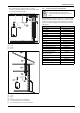
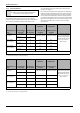
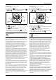
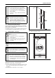
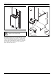
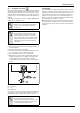
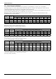
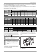
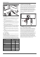
Table Of Contents
- Table of contents
- 1 Key to symbols and safety instructions
- 1.1 Key to symbols
- 1.2 Safety instructions
- 2 FCC rules
- 3 Appliance details
- 4 Installation instructions
- 4.1 Specialized tools
- 4.2 Introduction
- 4.3 Venting
- 4.3.1 Vent material
- 4.3.2 Vent specifications
- Condensate drain requirements
- Twin pipe termination clearances
- Minimum combustion air and exhaust pipe length
- Maximum combustion air and exhaust pipe length
- Use of elbows
- Calculation example for 3" venting:
- Calculation example for 4" venting:
- Required direct vent terminal clearances (twin pipe / concentric penetration)
- Required other than direct vent terminal clearances (single pipe penetration)
- 4.3.3 Vent configuration examples
- 4.3.4 Vent connections
- 4.3.5 Connecting the external condensate water drain
- 4.3.6 Freeze prevention
- 4.3.7 Venting for manufactured (mobile) homes
- 4.3.8 Fan speed adjustment
- 4.4 Combustion air requirements
- 4.5 Proper location for installing your heater
- 4.6 Heater placement and clearances
- 4.7 Hanging appliance on the wall
- 4.8 Mounting installation
- 4.9 Gas piping & connections
- 4.10 Water connections
- 4.11 Water quality
- 4.12 Domestic hot water recirculation
- 4.13 Space heating applications
- 4.14 Measuring gas pressure
- 5 Electrical connections
- 6 Operation instructions
- 7 Maintenance and service
- 8 Troubleshooting
- 9 Problem solving
- 10 Electrical diagram
- 11 Sensor resistance charts
- 12 Functional scheme
- 13 Interior components diagram and parts list
- 14 Protecting the environment
- 15 LIMITED TANKLESS HEATER WARRANTY
- 16 Installer Checklist to be completed by installer upon installation

Installation instructions
RTG 199 ME – 6 720 811 615 (2014/05)
21
• Do not install damper in unconditioned spaces (e.g. attics)
Condensation can build up while the heater is running which can later
freeze and potentially block the flapper
Fig. 25 Combustion air piping not shown for clarity purposes
[1] Good
[2] Better
[3] Best
Fig. 26 Combustion air piping not shown for clarity purposes
[1] Good
[2] Better
[3] Best
[4] Enclosed vent pipe (Do not install damper)
[5] Unconditioned space (Do not install damper)
[6] Preferred damper position for vertical terminations
4.3.7 Venting for manufactured (mobile) homes
When this appliance is installed in a mobile home, it is required that the
venting be installed such that all combustion air is provided from outside
the structure. As such, single pipe venting installations are forbidden in
mobile home installations. Appropriate flue gas venting parts are listed
in the table22:
WARNING:
▶ In a manufactured (mobile) home installation,
combustion air shall not be supplied from occupied
spaces.
3" Venting Z-flex Venting
24" Drain Tube Kit 2SVEDTK24
3" x 45° Elbow 2SVEEWCF0345
3" x 90° Elbow 2SVEEWCF0390
3" x 6" Pipe 2SVEPWCF03.5
3" x 12" Pipe 2SVEPWCF0301
3" x 18" Pipe 2SVEPWCF0301.5
3" x 2' Pipe 2SVEPWCF0302
3" x 3' Pipe 2SVEPWCF0303
3" x 4' Pipe 2SVEPWCF0304
Inline Vertical Tee 2SVEVDP03
3" Roof Flashing 0/12-6/12 2SVSADJF03
3" Roof Flashing 7/12-12/12 2SVSADJSF03
3" Rain Cap 2SVSRCF03
3" Custom Wall Thimble 2SVSWTCEC03
3" Exhaust/Intake Vent Hood
w/10" Sleeve (Qty 2)
2SVSTB03
3" Adjustable Adapter 4ZVAL03
3" Gear Clamps (Qty 2) 7HS44XX
3" Storm Collar 2SVSLSF03
Extreme Weather Termination* 2SVSHRC03
Horizontal Drain Tee 2SVEDWCF03
Table 22 Z-Flex Venting list