
Installation / Operation Instruction Manual
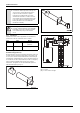
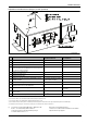
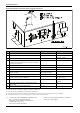
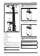
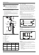
Table Of Contents
- Table of contents
- 1 Key to symbols and safety instructions
- 1.1 Key to symbols
- 1.2 Safety instructions
- 2 FCC rules
- 3 Appliance details
- 4 Installation instructions
- 4.1 Specialized tools
- 4.2 Introduction
- 4.3 Venting
- 4.3.1 Vent material
- 4.3.2 Vent specifications
- Condensate drain requirements
- Twin pipe termination clearances
- Minimum combustion air and exhaust pipe length
- Maximum combustion air and exhaust pipe length
- Use of elbows
- Calculation example for 3" venting:
- Calculation example for 4" venting:
- Required direct vent terminal clearances (twin pipe / concentric penetration)
- Required other than direct vent terminal clearances (single pipe penetration)
- 4.3.3 Vent configuration examples
- 4.3.4 Vent connections
- 4.3.5 Connecting the external condensate water drain
- 4.3.6 Freeze prevention
- 4.3.7 Venting for manufactured (mobile) homes
- 4.3.8 Fan speed adjustment
- 4.4 Combustion air requirements
- 4.5 Proper location for installing your heater
- 4.6 Heater placement and clearances
- 4.7 Hanging appliance on the wall
- 4.8 Mounting installation
- 4.9 Gas piping & connections
- 4.10 Water connections
- 4.11 Water quality
- 4.12 Domestic hot water recirculation
- 4.13 Space heating applications
- 4.14 Measuring gas pressure
- 5 Electrical connections
- 6 Operation instructions
- 7 Maintenance and service
- 8 Troubleshooting
- 9 Problem solving
- 10 Electrical diagram
- 11 Sensor resistance charts
- 12 Functional scheme
- 13 Interior components diagram and parts list
- 14 Protecting the environment
- 15 LIMITED TANKLESS HEATER WARRANTY
- 16 Installer Checklist to be completed by installer upon installation

Installation instructions
RTG 199 ME – 6 720 811 615 (2014/05)
15
Required direct vent terminal clearances (twin pipe / concentric penetration)
Fig. 11
[*] For clearances not specified in ANSI Z223.1 / NFPA 54 or CSA-
B149.1, one of the following shall be indicated:
a) A minimum clearance value determined by testing in
accordance with section 2.20, or;
b) A reference to the following footnote:
“Clearance in accordance with local installation codes and the
requirements of the gas supplier.”
Canadian installations
1)
U.S. installations
2)
A Clearance above grade, veranda, porch, deck or balcony 12 in. 12 in.
B Clearance to window or door that may be opened 36 in. 12 in.
C Clearance to permanently closed window * *
D Vertical clearance to ventilated soffit located above the vent
termination within a horizontal distance of 2 feet (61cm) from
the center line of the termination
**
E Clearance to unventilated soffit * *
F Clearance to outside corner * *
G Clearance to inside corner * *
H Clearance to each side of center line extended above meter/
regulator assembly
36 in. within a height 15 feet above
meter/ regulator assembly
*
I Clearance to service regulator vent outlet 36 in. *
J Clearance to non-mechanical air supply inlet to building or the
combustion air inlet to any other application
36 in. 12 in.
K Clearance to mechanical air supply inlet 72 in. 36 in. above if within 10 feet
horizontally
L Clearance above paved sidewalk or paved driveway located on
public property
84 in.
3)
*
M Clearance under veranda, porch deck or balcony 12 in.
4)
*
Table 19
1) In accordance with the current CSA B149.1 Natural Gas and Propane Installation Code.
2) In accordance with the current ANSI Z223.1 / NFPA 54 National Fuel Gas Code.
3) A vent shall not terminate directly above a sidewalk or paved driveway that is located between two single family dwellings and serves both dwellings.
4) Permitted only if veranda, porch, deck or balcony is fully open on a minimum of two sides beneath the floor.