
Installation / Operation Instruction Manual
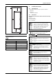
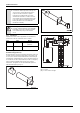
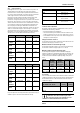
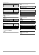
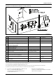
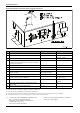
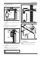
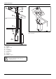
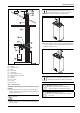
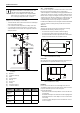
Table Of Contents
- Table of contents
- 1 Key to symbols and safety instructions
- 1.1 Key to symbols
- 1.2 Safety instructions
- 2 FCC rules
- 3 Appliance details
- 4 Installation instructions
- 4.1 Specialized tools
- 4.2 Introduction
- 4.3 Venting
- 4.3.1 Vent material
- 4.3.2 Vent specifications
- Condensate drain requirements
- Twin pipe termination clearances
- Minimum combustion air and exhaust pipe length
- Maximum combustion air and exhaust pipe length
- Use of elbows
- Calculation example for 3" venting:
- Calculation example for 4" venting:
- Required direct vent terminal clearances (twin pipe / concentric penetration)
- Required other than direct vent terminal clearances (single pipe penetration)
- 4.3.3 Vent configuration examples
- 4.3.4 Vent connections
- 4.3.5 Connecting the external condensate water drain
- 4.3.6 Freeze prevention
- 4.3.7 Venting for manufactured (mobile) homes
- 4.3.8 Fan speed adjustment
- 4.4 Combustion air requirements
- 4.5 Proper location for installing your heater
- 4.6 Heater placement and clearances
- 4.7 Hanging appliance on the wall
- 4.8 Mounting installation
- 4.9 Gas piping & connections
- 4.10 Water connections
- 4.11 Water quality
- 4.12 Domestic hot water recirculation
- 4.13 Space heating applications
- 4.14 Measuring gas pressure
- 5 Electrical connections
- 6 Operation instructions
- 7 Maintenance and service
- 8 Troubleshooting
- 9 Problem solving
- 10 Electrical diagram
- 11 Sensor resistance charts
- 12 Functional scheme
- 13 Interior components diagram and parts list
- 14 Protecting the environment
- 15 LIMITED TANKLESS HEATER WARRANTY
- 16 Installer Checklist to be completed by installer upon installation

Installation instructions
RTG 199 ME – 6 720 811 615 (2014/05)
13
4.3.2 Vent specifications
Install appliance as close to point of vent termination as possible. The
exhaust piping must vent directly to the outside of the structure.
Horizontal sections of vent must pitch upward towards termination ¼"
for every foot of horizontal length, to prevent the pooling of condensate,
and be supported at 4 foot intervals with overhead hangers.
Exception: horizontal run between last elbow and termination must
pitch down to termination 1/4" per foot. Note: For horizontal
terminations, venting must terminate once it penetrates to the outside of
the structure. There must be no sections of vent pipe exposed to the
outdoors other than the termination. Note: Listed thimbles or collars are
necessary where venting passes through wall and ceiling partitions. If
the vent system passes through combustible areas where the vent
clearance requirements cannot be maintained, consult local codes. The
distance to combustibles using this chase technique is 1 inch. Note:
Type-B vent must never be used as the actual exhaust vent system for
the appliance, as it is not gas tight and illegal for use with this appliance.
This will create a serious health hazard and void the warranty.
For specific questions concerning vent material, specifications, usage or
installation, please contact the vent manufacturer directly.
Condensate drain requirements
An external condensate drain (not supplied with the heater) must be
installed under the following conditions:
• All vertical terminating vent installations.
• Horizontal terminating vent installations where the total linear vent
length is greater than 10 feet (3.1 m) for 3" and 5 feet (1.5 m) for 4".
• Vent installations where any section of the exhaust vent pipe passes
through an unconditioned space.
Twin pipe termination clearances
The minimum clearance between exhaust vent and combustion air inlet
terminations for twin pipe penetration is 3 feet.
Minimum combustion air and exhaust pipe length
The minimum exhaust pipe length is 1 foot (0.3m) of straight vent pipe.
The minimum combustion air pipe length is one 90° elbow.
Maximum combustion air and exhaust pipe length
The following tables display the maximum allowable straight pipe
lengths for combustion air and exhaust piping with consideration to the
number of elbows used. Reduce the equivalent length for each elbow
used from the maximum allowable length depending on the system
used.
Use of elbows
It is recommended to limit the amount of elbows used in the exhaust and
combustion air piping to reduce friction in the air flow. The following lists
the maximum amount of 90° elbows allowed in either the exhaust or
combustion air piping:
Calculation example for 3" venting:
Exhaust
3" VENTING Z flex Protech Heat Fab
3"
90° elbow
2SVEEWCF0390 FSELB9003 9314
3" Tee
Terminal
2SVSTTF03 FSTT3 9390TEE
3" Horizontal
Terminal
2SVSTB03 FSTB3 N/A
3" horiz.
terminal
with damper
2SVSHTD03 N/A N/A
3" Vertical
Terminal
2SVSRCF03 FSRC3 5300CI
Table 6 3" Terminator Part Numbers
4" VENTING Z flex Protech Heat Fab
4"
90° elbow
2SVEEWCF0490 FSELB9004 9414
4" Tee
Terminal
2SVSTTF04 FSTT4 9490TEE
4" Horizontal
Terminal
2SVSTB04 FSTB4 N/A
4" horiz.
terminal
with damper
2SVSHTD04 FSRC4 5400CI
4" vertical
terminal
2SVSRCF04 N/A N/A
Table 7 4" Terminator Part Numbers
Company Contact info
Z-flex www.z-flex.com
800-654-5600
ProTech Industries www.protechinfo.com
800-766-3473
Heat-Fab www.heatfab.com
800-772-0739
Table 8 Vent manufacturers
Venting Maximum
allowable
Exhaust pipe
length
Maximum
allowable
Combustion air
pipe length
Elbow Equivalency
90° 45°
3" 28.5 ft 28.5 ft 2.5 ft 1.25 ft
4" 61.25 ft 61.25 ft 1.25 ft 0.75 ft
Table 9 Maximum Allowable Exhaust and Combustion Air Lengths
Max. number of 90° elbows 3" venting 4" venting
Max number of elbows 5 7
Table 10
Two 45° elbows are equal to one 90° elbow. Any
combination of 45° and 90° elbows may be used in
the vent system as long as the combination does not
exceed the maximum listed in table 9 above.