
Installation / Operation Instruction Manual
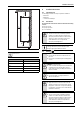
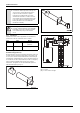
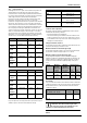
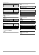
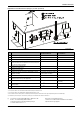
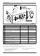
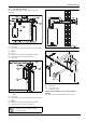
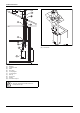
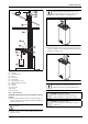
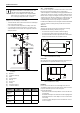
Table Of Contents
- Table of contents
- 1 Key to symbols and safety instructions
- 1.1 Key to symbols
- 1.2 Safety instructions
- 2 FCC rules
- 3 Appliance details
- 4 Installation instructions
- 4.1 Specialized tools
- 4.2 Introduction
- 4.3 Venting
- 4.3.1 Vent material
- 4.3.2 Vent specifications
- Condensate drain requirements
- Twin pipe termination clearances
- Minimum combustion air and exhaust pipe length
- Maximum combustion air and exhaust pipe length
- Use of elbows
- Calculation example for 3" venting:
- Calculation example for 4" venting:
- Required direct vent terminal clearances (twin pipe / concentric penetration)
- Required other than direct vent terminal clearances (single pipe penetration)
- 4.3.3 Vent configuration examples
- 4.3.4 Vent connections
- 4.3.5 Connecting the external condensate water drain
- 4.3.6 Freeze prevention
- 4.3.7 Venting for manufactured (mobile) homes
- 4.3.8 Fan speed adjustment
- 4.4 Combustion air requirements
- 4.5 Proper location for installing your heater
- 4.6 Heater placement and clearances
- 4.7 Hanging appliance on the wall
- 4.8 Mounting installation
- 4.9 Gas piping & connections
- 4.10 Water connections
- 4.11 Water quality
- 4.12 Domestic hot water recirculation
- 4.13 Space heating applications
- 4.14 Measuring gas pressure
- 5 Electrical connections
- 6 Operation instructions
- 7 Maintenance and service
- 8 Troubleshooting
- 9 Problem solving
- 10 Electrical diagram
- 11 Sensor resistance charts
- 12 Functional scheme
- 13 Interior components diagram and parts list
- 14 Protecting the environment
- 15 LIMITED TANKLESS HEATER WARRANTY
- 16 Installer Checklist to be completed by installer upon installation

Installation instructions
RTG 199 ME – 6 720 811 615 (2014/05)
12
4.3.1 Vent material
Establish vent clearances that comply with the vent manufacturer's
specifications. In all cases, follow local codes. See table 5:
Horizontal venting systems only:
An optional stainless concentric vent/air intake termination can be used
to provide only one penetration point through the exterior wall (see fig.
8, 9 & 10). The concentric vent/air intake kit can be ordered from your
local wholesaler. (Part# ESHCK). Note: Only tee terminals are approved
for use with the concentric vent/air intake kit (see Table 6). Vent piping
and tee terminal used with kit must be from the same vent pipe
manufacturer. The appliance can also be installed with separate air
intake and exhaust piping (see Fig.16).
Fig. 8 Concentric kit part # ESHCK
Fig. 9 Concentric kit vent assembly
Fig. 10 Concentric kit installation
[LA] 12 inches
[LB] 3 inches stainless steel pipe
NOTICE:
▶ In areas where outside temperatures routinely come
close to freezing, sealed combustion operation is
required. Concentric termination or separate
terminations for combustion and vent, must be
installed on the same wall or roof surface; however,
never facing the direction of prevailing winds. Failure
to do so may result in heat exchanger freezing and
bursting. This failure is not covered under the
manufacturer's warranty.
WARNING: Appliance malfunction!
▶ Protect the exhaust and inlet from leaves and debris
by installing a screen on the end of the termination.
¼ " mesh minimum opening recommended on
screen.
Item Diam. Material
Exhaust Vent 3 or 4 inches Sealed single wall stainless steel
(AL29-4C)
Intake Vent PVC Sealed PVC or any other rigid pipe
Table 5 Venting Specifications