Installation and Operation instructions INDOOR MODEL RTG 199 ME Warning: If the information in this manual is not followed exactly, a fire or explosion may result causing property damage, personal injury or death. Do not store or use gasoline or other flammable vapors and liquids in the vicinity of this or any other appliance. Installation and service must be performed by a trained and certified installer, service agency or the gas supplier.
Table of contents Table of contents 1 Key to symbols and safety instructions . . . . . . . . . . . . . . . . . . . 3 1.1 Key to symbols . . . . . . . . . . . . . . . . . . . . . . . . . . . . . . . . . 3 1.2 Safety instructions . . . . . . . . . . . . . . . . . . . . . . . . . . . . . . 3 2 FCC rules . . . . . . . . . . . . . . . . . . . . . . . . . . . . . . . . . . . . . . . . . . . . . 6 3 Appliance details . . . . . . . . . . . . . . . . . . . . . . . . . . . . . . . . . . . . . . 7 3.1 Features .
Key to symbols and safety instructions 1 Key to symbols and safety instructions 1.1 Key to symbols Warnings Warnings in this document are identified by a warning triangle printed against a grey background. Keywords at the start of a warning indicate the type and seriousness of the ensuing risk if measures to prevent the risk are not taken.
Key to symbols and safety instructions Risk of scalding at the hot water draw-off point ▶ When the water heater is in operation, temperatures in excess of 122 °F (50 °C) can occur. To limit the temperature at the tap, install a thermostatic DHW mixing valve. ▶ Water heated for washing the laundry, dishes and for other cleaning purposes can cause scalding and permanent injuries. ▶ Children, elderly, and handicapped persons are more likely to be permanently injured by hot water.
Key to symbols and safety instructions For your safety ▶ Do not store or use gasoline or other flammable, combustible or corrosive vapors and liquids in the vicinity of this or any other appliance. DANGER: Fatal accidents! Carbon monoxide poisoning. ▶ Carefully plan where you install the heater. Correct combustion air supply and flue pipe installation are very important. If a gas appliance is not installed correctly, fatal accidents can result such as carbon monoxide poisoning or fire.
FCC rules WARNING: Personal Injury from toxic chemicals. ▶ A water heater which will be used to supply potable water shall not be connected to any heating system or component(s) previously used with a nonpotable water heating appliance. WARNING: Installation in mobile homes. ▶ Installation in mobile homes shall conform to Title 24 CFR, part 3280 and/or CAN/CSA Z240 MH Series, Mobile Homes. 2 FCC rules FCC: This device complies with Part 15 of the FCC rules.
Appliance details 3 Appliance details 3.1 Features Parts • Key Pad interface control. • High power pre-mix compact burner with low NOx emissions. • Modulating Gas Valve with constant gas:air ratio control. • Modulating water valve for improved comfort and temperature control. High quality materials for long working life • Copper heat exchanger. • High efficiency Ceramat Burner. • Compact space saver: mounts on a wall with a supplied bracket. Features • Easily removable one-piece cover.
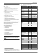
Appliance details • Energy Guide label (in the front cover) Technical characteristics Natural Gas Units RTG 199 ME V AC 120 Hz 60 mA 40 A 2.5 db (A) 45 - 65 IP X4D LP Gas Voltage Nominal Frequency Amperage Idle Operation Noise Water protection3) The RTG 199ME is not approved or designed for: • Manufactured (mobile) homes, boats or any mobile installation. (Modular homes are acceptable for installation). • Use above 8000 ft A.S.L. altitude (see page 22).
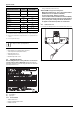
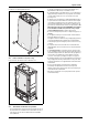
Appliance details ▶ Lift front cover panel upward and remove. • • • • • • Fig. 4 Remove the front cover 3.3.3 Remove combustion cover (service only) ▶ Open the four clips and remove the combustion cover. • • • In Canada: The Installation must conform with CSA B149.(1,2) INSTALLATION CODES and /or local installation codes. 2. Carefully plan where you install the heater. Correct combustion air supply and vent pipe installation are very important.
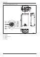
Appliance details 3.5 Dimensions and minimum installation clearances Fig.
Installation instructions 4 Installation instructions 4.1 Specialized tools The following specialized tools may be required for installation: • Manometer • Multi-meter • Combustion Gas Analyzer 4.2 Introduction Please follow these instructions. Failure to follow instructions may result in: ▶ Damage or injury. ▶ Improper operation. ▶ Loss of warranty. DANGER: ▶ The water heater must be installed by a qualified installer in accordance with these instructions.
Installation instructions NOTICE: ▶ In areas where outside temperatures routinely come close to freezing, sealed combustion operation is required. Concentric termination or separate terminations for combustion and vent, must be installed on the same wall or roof surface; however, never facing the direction of prevailing winds. Failure to do so may result in heat exchanger freezing and bursting. This failure is not covered under the manufacturer's warranty.
Installation instructions 4.3.2 Vent specifications Install appliance as close to point of vent termination as possible. The exhaust piping must vent directly to the outside of the structure. Horizontal sections of vent must pitch upward towards termination ¼" for every foot of horizontal length, to prevent the pooling of condensate, and be supported at 4 foot intervals with overhead hangers. Exception: horizontal run between last elbow and termination must pitch down to termination 1/4" per foot.
Installation instructions System used Number of 90° elbows needed: Number of 45° elbows needed: Concentric 1 2 Table 11 Calculation of example Max. length 90° elbow reduction sub-total = 45° elbow reduction Total = Calculation example for 4" venting: Exhaust System used Number of 90° elbows needed: Number of 45° elbows needed: Twin pipe 2 2 Table 15 28.5’ - 2.5’ 26’ - 2.5’ 23.5’ Table 12 For this example, the maximum allowable exhaust pipe length is 23.5 feet. Calculation of example Max.
Installation instructions Required direct vent terminal clearances (twin pipe / concentric penetration) Fig. 11 A Clearance above grade, veranda, porch, deck or balcony Canadian installations1) 12 in. B Clearance to window or door that may be opened 36 in. 12 in.
Installation instructions Required other than direct vent terminal clearances (single pipe penetration) Fig. 12 A Clearance above grade, veranda, porch, deck or balcony Canadian installations1) 12 in. B Clearance to window or door that may be opened 36 in.
Installation instructions 4.3.3 Vent configuration examples Below are approved examples of vertical and horizontal venting installations. Fig. 13 Horizontal side wall venting installation (single pipe penetration) [1] [2] [3] [4] [5] [6] [7] Termination Minimum above ground or normally expected snow accumulation level Appliance Drain tee Elbow (note: minimum 1ft of straight vent pipe required) Horizontal run ¼ " per foot down to termination Hanger strap Fig.
Installation instructions Fig. 18 [LA] 3ft minimum Fig.
Installation instructions NOTE: Vent pipe must be completely vertical when inserting or blue gasket inside exhaust accessory can become displaced. Exhaust accessory can be removed with vent pipe attached to check gasket position. Fig. 20 Exhaust connection ▶ Attach the combustion air inlet accessory to the top of the unit fig. 21 (position 2) using the 3 screws and gasket provided, and install 3" air intake pipe over the accessory. Fig. 19 [1] [2] [3] [4] [5] [6] [7] [8] [9] [10] [11] [12] 4.3.
Installation instructions Use materials approved by the authority having jurisdiction. In the absence of other authority, PVC, and CPVC pipe must comply with ASTM D1785, F441 orD2665. Cement and primer must comply with ASTM D2564 or F493. For Canada, use CSA or ULC certified PVC or CPVC pipe, fittings and cement, see table 5. If an external condensate drain (installer supplied) must be installed (chapter 4.3.2), the following is recommended: • 1.
Installation instructions • Do not install damper in unconditioned spaces (e.g. attics) Condensation can build up while the heater is running which can later freeze and potentially block the flapper 4.3.7 Venting for manufactured (mobile) homes WARNING: ▶ In a manufactured (mobile) home installation, combustion air shall not be supplied from occupied spaces.
Installation instructions 4.3.8 necessary adjustments to fan speed values may result in improper operation of the appliance. Fan speed adjustment NOTICE: IMPORTANT INFORMATION! ▶ Natural gas heaters with installation altitudes below 2,000 ft above sea level disregard this section. Installation adjustment: After installing the tankless water heater, the fan speed values for minimum power (P2) and maximum power (P1) may need adjustment due to variations in altitude and vent pipe length.
Installation instructions Adjusting minimum power fan speed (P2) To select fan speed: ▶ Press ON/OFF button into ON. ▶ Immediately following, press and hold simultaneously buttons + or and P for 3 seconds, until display reads P2. Adjusting maximum power fan speed (P1) To select fan speed: Fig. 27 Fig. 28 ▶ Press P to enter P2 adjustment. The current setting will appear on the display (factory default). ▶ Press + or to choose the fan speed suitable with your installation, see table 23 and table 24.
Installation instructions 1. The referenced "special venting system" instructions shall be included with the appliance or equipment installation instructions; and 2. The "special venting systems" shall be product approved by the Board, and the instructions for that system shall include a parts list and detailed installation instructions.
Installation instructions NOTICE: Risk of appliance freezing! ▶ The water in this water heater is cold and always remains cold except for the times the burner is on. In the event of power outage in conjunction with freezing temperatures, it is recommended that the heater be drained. See chapter 7.2, page 37 “Winterizing” for draining instructions.
Installation instructions 6720608158-05.1AL Fig. 31 Mounting the heater CAUTION: Personal injury and property damage. ▶ Appliance must be installed vertically. 4.8 Mounting installation Fig. 32 Mounting the heater When installing this appliance the unit must be additionally secured at the bottom of the water heater as shown in fig. 32. Use the included screws to secure the brackets at the bottom of the water heater to the wall.
Installation instructions 4.9 Gas piping & connections Before connecting the gas supply, check the rating plate on the right side of the heater to be sure that the heater is rated for the same gas to which it will be connected. Example rating plate can be found in fig. 2, page 8. In the United States: The installation must conform with local codes or, in the absence of local codes, the National Fuel Gas Code ANSI Z223.1/ NFPA 54.
Installation instructions 4.9.1 Gas Line Sizing Tables for NATURAL GAS For your convenience see below for an excerpt from gas line sizing tables for a single NG appliance. For details see the current NFPA 54. Specified pipe lengths are for one RTG 199ME, which has a maximum input rating of 199,000 BTUs. The gas supply system must be sized for the combined total maximum BTU/hr load requirements of all gas appliances running simultaneously.
Installation instructions 4.9.2 Gas Line Sizing Tables for LP GAS For your convenience see below for an excerpt from gas line sizing tables for a single LP appliance. Their intended use of is for pipe sizing between the 2nd stage (low pressure) regulator and the appliance. For details see the current NFPA 54 or NFPA 58. Specified pipe lengths are for one RTG 199ME which has a maximum input of 199,000.
Installation instructions Connecting the pressure relief valve (PRV) A listed pressure relief valve must be installed at the time of installation. No valve is to be placed between the PRV and the heater. No reducing coupling or other restriction may be installed in the discharge line. The discharge line must be a minimum of 4” above a drain and installed such that it allows complete drainage of both the PRV and the line. The discharge line must be placed where it will not cause any damage.
Installation instructions CAUTION: ▶ Propylene glycol may be used for freeze prevention ONLY on the space heating side of the heat exchanger. Do not use ethylene glycol (automotive antifreeze). CAUTION: ▶ The use of a flow switch is recommended to ensure DHW priority and to prevent “cold-blow” situations when the tankless water heater is used with an airhandling system. The flow switch should be used to disable the blower on the air-handling system when domestic water is used. Fig.
Installation instructions Fig. 39 Space heating diagram [1] [2] [3] [4] [5] [6] [7] [8] [9] [10] [11] [12] [13] [14] [17] [18] [19] [20] [21] [22] 4.
Electrical connections ▶ Record lowest operating gas pressure reading in table 33. Gas pressures lower than 3.5" W.C. for Natural Gas or 8" W.C. for LPG will result in insufficient degree rise to the hot water being used, reduced hot water volume, possible error code faults and must be corrected. See Gas Connections, chapter 4.9, page 27. P1 fan speed: Factory default: NG: 48, LP: 40 Lowering P1 fan speed reduces the maximum BTU input.
Operation instructions ▶ Check the fuses in the printed circuit board, see fig. 44, pos. 3. ▶ After checking the fuses, reinstall all parts in reverse order. Fig. 44 Fuses position 6 Operation instructions Fig. 45 [1] [2] [3] [4] [5] [6] [7] 6.1 On/Off button Reset button Program Key LCD display Up button Down button Power On or stand-by LED Description LCD Display WARNING: ▶ Do not use any cleaning aggressive or corrosive agents to clean the window. Fig. 46 Power bar indicator (input) Fig.
Operation instructions Fig. 48 Error indicator WHAT TO DO IF YOU SMELL GAS ▶ Turn off the gas shut-off valve. ▶ Open windows and doors. ▶ Do not try to light the appliance. ▶ Do not touch any electrical switch, telephone, and do not use outlets. ▶ Extinguish all open flames. Do not smoke! Do not use lighters! ▶ Warn all occupants of the building. Do not ring doorbells! ▶ If you can hear gas leaking, leave the building immediately.
Operation instructions this symptom, clean fixtures or replace with higher flowing ones if necessary. ▶ LCD flashes until selected temperature is reached. ▶ Power bar indicates power percentage in use. Saving water resources: ▶ Make sure you close all the taps after any use. Avoid leaving the taps dripping. Repair any leaking tap. ▶ Define the temperature you want, in the appliance or with the remote control.
Maintenance and service Inlet Water Filter • Verify the inlet filter screen is clean and undamaged. The inlet water filter is located on the bottom of the appliance, to the right of the cold water inlet fitting. (See Fig.35, page 30). Close installer supplied water shutoff and remove wireform spring clip from filter. Remove filter, clean and or replace if damaged Fig.
Maintenance and service ▶ Using a 3rd line (C) from the descaling reservoir, connect to the inlet side of circulating pump. Install a filter on the end of the line in the descaling reservoir. ▶ Make sure all connections are "water tight.". ▶ Fill tank with descaling solution so both lines inside are submersed. We recommend a straight white vinegar solution. If using a commercial descalant, refer to manufacturer's instructions for proper dilution ratio. ▶ Operate the circulating pump.
Maintenance and service Max. CO level CO2 range (%) (measured) Nat. Gas max. input P1 6.3 % - 6.9 % < 250 ppm min. input P2 2.3 % - 2.6 % < 60 ppm max. input P1 8.7 % - 9.3 % < 250 ppm min. input P2 2.7 % - 3.0 % < 60 ppm LP Gas * Values above are for climate controlled conditions. Inputs such as gas pressure, heating value of the gas, humidity and temperature of combustion air all impact CO and CO2 values.
Maintenance and service 7.5 Program values Refer to chapter 7.6 Control board diagnostics (page 41) regarding how to access these P-modes. This section describes details on programming the appliance. For most applications the factory default values will provide robust and stable operation. Only adjust the factory settings if the installation requires changes as indicated in the appropriate section of this manual.
Maintenance and service 7.6 Control board diagnostics 1. Press ON/OFF button into ON. 2. Immediately following, press and hold simultaneously buttons + or and P for 3 seconds, until display reads P2. 3. Press P to enter P2 adjustment. The current setting will appear on the display. If not, repeat process. 4. Press and release the P button on the control panel until the display reads 'P4'. You are now in the diagnostic mode of the control board. 5.
Troubleshooting 8 Troubleshooting CAUTION: ▶ If you are unable to perform the tasks listed below, or need additional assistance please contact your original installer or a licensed gas technician. 8.1 Introduction Many of the questions customers ask regarding operation of this unit can be answered by following the troubleshooting steps as outlined below. For best results, perform each step before proceeding to the next. The suggested solutions may require that the cover be taken off. (See fig.
Troubleshooting 8.6 Hot water temperature fluctuates at tap 1. Hot water is very hot out of the water heater, requiring mixing in cold water in order to attain a usable hot water temperature. The addition of too much cold will overpower hot water flow from the tankless water heater. If this slows the flow through the tankless water heater below its activation point, it will shut off the burners. The end result is nothing but cold water coming out of the outlet. 2. Unbalanced pressure in water lines.
Problem solving 9 Problem solving 9.1 Error code diagnostics To remove error code from the display, press the reset button. Display (Flashing) Cause Fault in the flue gas limiter. Temperature above 230°F (110 °C) inside the cabinet. Solution 1. Check continuity of the flue gas limiter (see fig. 70, page 50). Go to steps two and three to determine flue gas limiter fault and repair it. 2.
Problem solving Display Cause Solution No rotational speed sensor signal from 1. Disconnect power supply cord and check wire connections on back side of fan and primary fan. the two connectors on the control board, see fig. 77, #6, page 57. 2. Check supply voltage. It must be 120VAC and properly grounded. 3. Possible defective component in fan or defective control unit call manufacturer for further instructions. (Flashing) Water flow signal over specified maximum value. Water flow > 10 gallon/min.
Problem solving Display Cause No flame ionization detected with water flow. Solution 1. Verify that all manual gas shut off valves are open. 2. Check gas type. See fig. 2, page 8. 3. Reset error code and open a water tap to cycle the heater in an effort to purge air. Cycling hot water tap on and off multiple times may be necessary. If heater still faults with EA error code, have a licensed gas technician properly purge air out of the gas line leading to the water heater. 4.
Electrical diagram 10 Electrical diagram 16 20 15 13 M M 12 M E PS 11 10 19 T=104°C T=220°F 18 9 T=110°C T=230°F 8 FS 7 6 Casc. 5 input Casc. 4 output Back flow 3 2 1 17 16 21 14 ... 1 20 ... JP2 JP7 JP5 1 JP8 JP6 22 6720608158-92.1AL Fig.
Sensor resistance charts 11 Sensor resistance charts Fig. 67 Outlet / Inlet immersion sensor characteristics Fig.
Functional scheme 12 Functional scheme Fig.
Interior components diagram and parts list 13 Interior components diagram and parts list 13.1 Interior components Fig.
Interior components diagram and parts list Fig.
Interior components diagram and parts list 13.2 Components diagram 13.2.1 Group 1 Fig.
Interior components diagram and parts list 13.2.2 Group 2 Fig.
Interior components diagram and parts list 13.2.3 Group 3 Fig.
Interior components diagram and parts list 13.2.4 Group 4 Fig.
Interior components diagram and parts list 13.2.5 Group 5 Fig.
Interior components diagram and parts list 13.2.6 Group 6 Fig. 77 Components Diagram Item 1 2 3 4 5 6 7 9 Description Control unit Fuse T2.5A Fuse T1.
Protecting the environment 14 Protecting the environment Packing The packing box may be fully recycled as confirmed by the recycling symbol . Components Many parts in the heater can be fully recycled in the end of the product life. Contact your city authorities for information about the disposal of recyclable products. Saving water resources: ▶ Make sure you close all the taps after any use. Avoid leaving the taps dripping. Repair any leaking tap.
LIMITED TANKLESS HEATER WARRANTY 15 LIMITED TANKLESS HEATER WARRANTY BRADFORD WHITE CORPORATION LIMITED TANKLESS HEATER WARRANTY WHAT DOES THIS LIMITED WARRANTY COVER? This limited warranty covers both the heat exchanger and component parts for leakage or other malfunction caused by defects in materials and/or workmanship.
LIMITED TANKLESS HEATER WARRANTY LIMITED TANKLESS HEATER WARRANTY (CONTINUED) WHAT WILL WE DO TO CORRECT PROBLEMS? 1. If a defect occurs within the heat exchanger warranty period, we will: Provide a replacement heater of our manufacture, (or at our option) repair any unit, which develops a leak in the heat exchanger within the warranty period. To obtain a replacement, you must forward both the rating plate from the defective unit to us and a copy of the original sales receipt.
Installer Checklist to be completed by installer upon installation 16 Installer Checklist to be completed by installer upon installation Serial Number (8 digit serial number is located on rating plate on right side panel) ___ ___ ___ ___ ___ ___ ___ ___ Gas Pressure Reading 1) Static Operating Water Pressure Building Water Pressure Range if on Well system Installing Company Installer name Address Phone Table 48 1) See Chapter 4.
Notes 62 RTG 199 ME – 6 720 811 615 (2014/05)
Notes RTG 199 ME – 6 720 811 615 (2014/05) 63